Medical Bipolar Electrode Assembly With A Cannula Having A Bipolar Active Tip And A Separate Supply Electrode And Medical Monopolar Electrode Assembly With A Cannula Having A Monopolar Active Tip And A Separate Temperature-Transducer Post

Active Publication Date: 2007-01-18
STRYKER CORP
View PDF62 Cites 189 Cited by
  • Summary
  • Abstract
  • Description
  • Claims
  • Application Information

AI Technical Summary

Benefits of technology

[0021] Based on the data read from the cannula supply electrode memories, the control console also regulates the RF signal that is applied to the supply electrode in order to energize the cannulae active tip(s).
[0022] In some versions of the invention, when a supply electrode or post is first select

Problems solved by technology

However, to date, there have been obstacles to using bipolar electrodes for denervation procedures.
This is because it has proven difficult to provide bipolar electrode assemblies that are relatively small in size.
Large diameter electrodes, with sections having diff

Method used


Image

  • Medical Bipolar Electrode Assembly With A Cannula Having A Bipolar Active Tip And A Separate Supply Electrode And Medical Monopolar Electrode Assembly With A Cannula Having A Monopolar Active Tip And A Separate Temperature-Transducer Post
  • Medical Bipolar Electrode Assembly With A Cannula Having A Bipolar Active Tip And A Separate Supply Electrode And Medical Monopolar Electrode Assembly With A Cannula Having A Monopolar Active Tip And A Separate Temperature-Transducer Post
  • Medical Bipolar Electrode Assembly With A Cannula Having A Bipolar Active Tip And A Separate Supply Electrode And Medical Monopolar Electrode Assembly With A Cannula Having A Monopolar Active Tip And A Separate Temperature-Transducer Post

Examples


Embodiment Construction

[0047] I. OVERVIEW

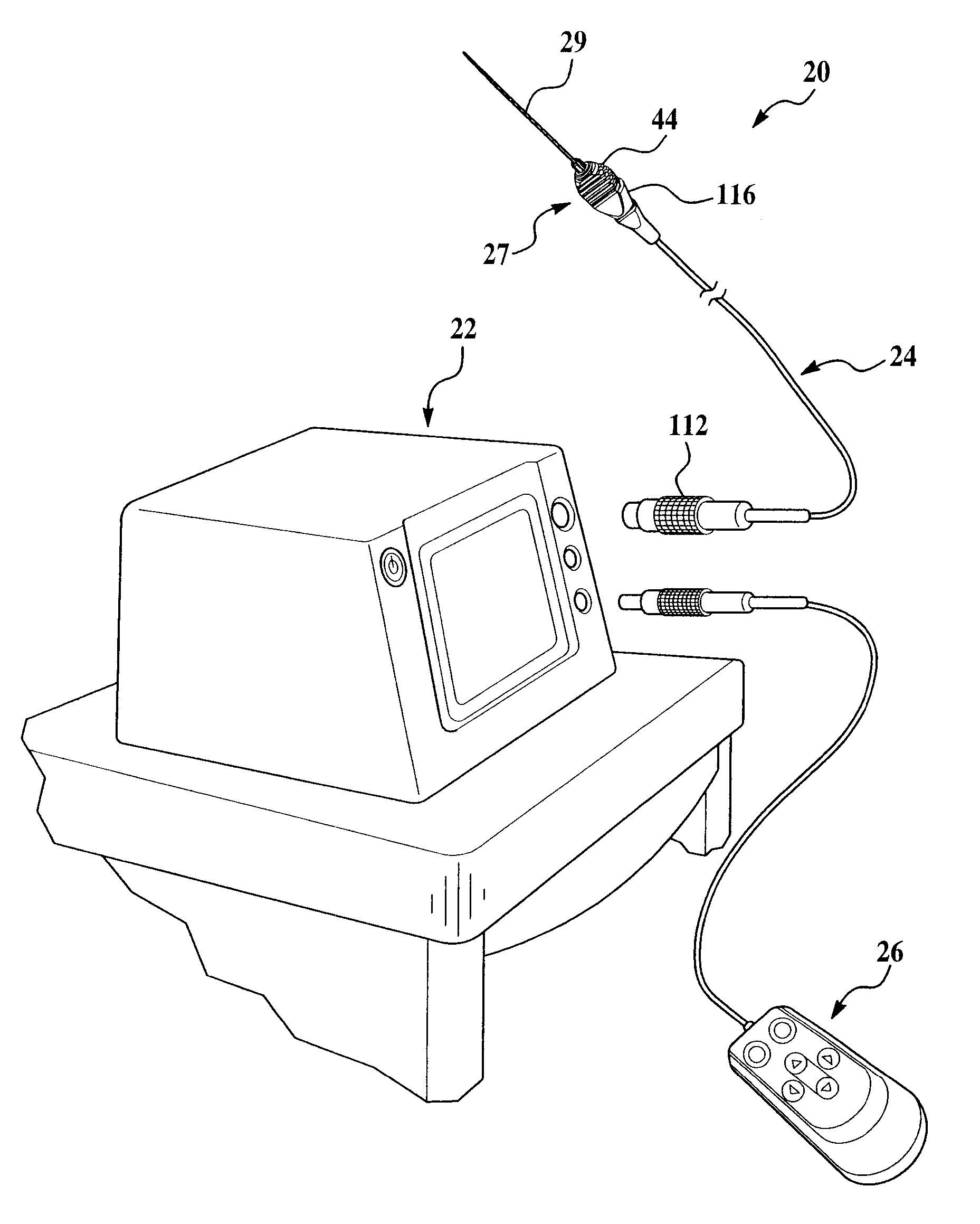
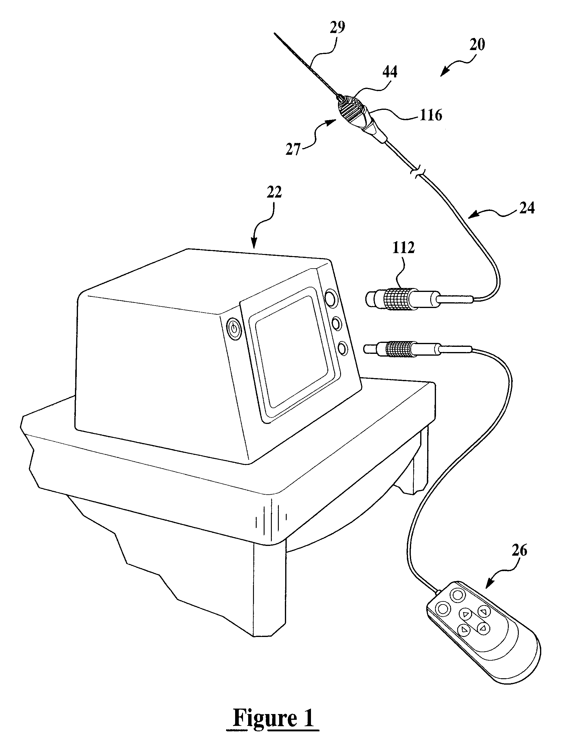
[0048] Referring in more detail to the drawings, FIG. 1 illustrates a bipolar electrosurgical system 20 of the present invention having a control console 22 for generating electrical energy of a controlled radiofrequency. An electrode assembly 24 (also referred to as an electrosurgical tool or electrode tool) of the system 20 plugs into the control console 22 at one end and delivers the radio frequency (RF) energy to a targeted nerve tissue area of a patient at an opposite end. Preferably, the system 20 has a remotely located controller 26 that communicates with and preferably plugs into the control console 22 enabling an operating physician to control multiple functions. Further aspects of the control console 22 are disclosed in U.S. patent application, serial number 11 / 112,702, having the same assignee as the present invention and incorporated herein by reference in its entirety.

[0049] In a pain management procedure, system 20 is used to modify nerve cells to t...


PUM


Abstract

An electrosurgical system preferably used for denervation procedures of nerve tissue has a control unit and a pluggable electrode assembly. The electrode assembly has a preferably disposable cannula and a preservable supply electrode assembly. The cannula has a tubular body that projects axially from a preferably pointed distal end for piercing tissue to a proximal end engaged to a first coupling assembly of the cannula. The body carries a first contact exposed directly to the nerve tissue and connected electrically to a terminal of the first coupling assembly. The supply electrode assembly has a second coupling assembly and a supply electrode that projects axially and removably into a through-bore of the body when the tool is in an operating state. The second coupling assembly carries a terminal that abuts the first coupling assembly when the coupling assemblies are mated. Preferably the supply electrode carries a temperature sensor for temperature measurement of the targeted tissue and processing by the control unit. Preferably, the electrode assembly also includes a stylet having a rod that fits into the through-bore of the body when the supply electrode assembly is removed and the tool is in a tissue penetrating state.

Description

CROSS-REFERENCE TO RELATED APPLICATIONS [0001] This application claims priority under 35 U.S.C. §119 from U.S. Provisional Patent Application No. 60 / 676,092, filed Apr. 29, 2005, the advantages and disclosure of which is hereby incorporated by reference.FIELD OF THE INVENTION [0002] This invention is related generally to an electrode assembly such as an electrode assembly that can be used to perform a denervation procedure. One version of this invention is related to a bipolar electrode assembly that can further be employed to introduce therapeutic agents at the site to which the electrode is applied. BACKGROUND OF THE INVENTION [0003] Electrosurgical tool systems are used to cut tissue, shape tissue, coagulate tissue and ablate tissue at surgical sites to which the tools are applied. Generally, an electrosurgical tool system includes an electrode with at least one electrically active tip. An electrode that has a single active tip is referred to as monopolar. An electrode with at le...

Claims


Application Information

Patent Timeline
IPC IPC(8): A61B18/18
CPCA61B18/1477A61B2017/00212A61B2017/00867C08L2201/12A61B2018/0044A61B2018/00821A61B2018/00434
Inventor TULLIS, PHILIP JAMESGAMHEWAGE, CHAMARASTAUNTON, DOUGLAS ALANCRAMLET, ELANDFICKES, NICOLESTAATS, ANDY
Owner STRYKER CORP
Why Eureka
Try Eureka