Switch mechanisms for safe activation of energy on an electrosurgical instrument

a technology of safe activation and switch mechanism, which is applied in the field of switch mechanism for safe activation of energy on an electrosurgical instrument, can solve the problems of reducing affecting the efficiency of contacts, and affecting the safety of the switch mechanism

Active Publication Date: 2007-01-18
COVIDIEN AG
View PDF98 Cites 261 Cited by
  • Summary
  • Abstract
  • Description
  • Claims
  • Application Information

AI Technical Summary

Benefits of technology

[0008] In one embodiment, the actuator includes a driver having a first connector for engagement with the pair of high-energy contacts and a second connector for engagement with the pair of activation contacts. The actuator includes a biasing member positioned between the first and second connectors. The actuator can be vertically or horizontally movable.
[0009] In another embodiment, the actuator includes a first wiper and a second wiper, the first and second wiper are spaced apart such that the first wiper contacts the first high-energy contact in advance of the second wiper contacting the first activation contact. The second high-energy contact and the second activation contact are a common contact.
[0010] In one embodiment, the actuator includes a driver having a first elongated drive surface for engagement with the first high-energy contact and a second elongated drive surface for engagement with the second high-energy contact. The first elongated drive surface is substantially longer than the second elongated drive surface to insure that contact wit

Problems solved by technology

Issues may arise within the switch mechanism itself during activation of the electrosurgical instrument.
However, due to the nature of these materials, they are susceptible to damage as the contacts are brought together while energized.
This arcing often results in damage to the high-energy contacts themselves reducing the efficiency of the contacts.
Furthermore, during most surgical procedures utilizing electro

Method used


Image

  • Switch mechanisms for safe activation of energy on an electrosurgical instrument
  • Switch mechanisms for safe activation of energy on an electrosurgical instrument
  • Switch mechanisms for safe activation of energy on an electrosurgical instrument

Examples


Embodiment Construction

[0023] Embodiments of the presently disclosed switching mechanisms will now be described in detail with reference to the drawings wherein like numerals designate identical or corresponding elements in each of the several views. As is common in the art, the term ‘proximal” refers to that part or component closer to the user or operator, i.e. surgeon or physician, while the term “distal” refers to that part or component further away from the user.

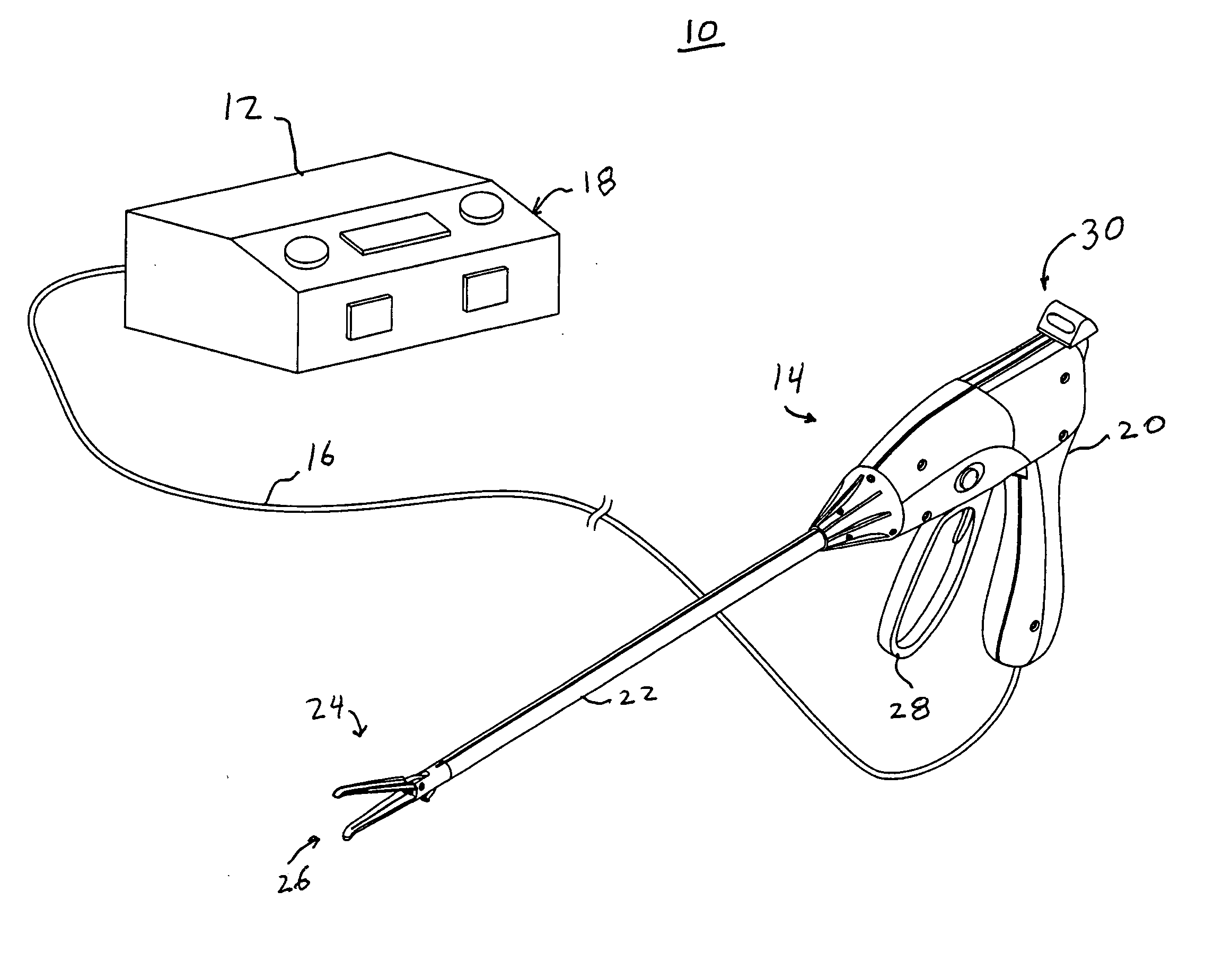
[0024] Referring to FIG. 1, there is disclosed an embodiment of an electrosurgical instrument assembly 10 of the type used during certain surgical procedures. Electrosurgical instrument assembly 10 generally includes an energy generator 12 and an electrosurgical instrument 14 connected by a transmission cable 16. Energy generator 12 may supply various sources of “high” energy to the electrosurgical instrument 14. As used herein, the term “high-energy” refers to various sources of energy, i.e. high current / high voltage, applied to tissue duri...


PUM


Abstract

Various safe switching mechanisms are provided for use with electrosurgical instruments which prevent arcing between the high-energy contacts as the high-energy source is activated. The switching mechanisms generally include a pair of high-energy contacts and a pair of activation contacts. An actuator is provided which initially engages the high-energy contacts in advance of engagement of the activation contacts to prevent arcing and subsequently disengages the activation contacts in advance of the high-energy contacts as the energy source is deactivated. A method of switching power to an electrosurgical instrument while avoiding damage to high-energy contacts is also disclosed.

Description

BACKGROUND [0001] 1. Technical field [0002] The present disclosure relates to switch mechanisms for safe activation of energy on an electrosurgical instrument. More particularly, the present disclosure relates to switching mechanisms for engaging high energy contacts prior to activation of the energy source. [0003] 2. Background of Related Art [0004] Many surgical procedures are enhanced by the use of energy during the procedure. Special surgical instruments have been developed to utilize the energy during the surgical procedures. These instruments are typically termed “electrosurgical instruments” and include provisions for utilizing energy to cauterize, cut, etc. tissue during various surgical procedures. Typically, during these surgical procedures, a distal portion of the electrosurgical instrument is engaged with tissue and the energy source turned on, or activated, by a switching mechanism to supply the energy to tissue. The energy applied to the tissue may take various forms i...

Claims


Application Information

Patent Timeline
IPC IPC(8): A61B18/14
CPCA61B18/14A61B18/1445H01H2300/014H01H9/0066H01H13/64A61B2017/00973
Inventor WEINBERG, CRAIGSHARP, ROBERTCOUTURE, GARY M.ODOM, DARREN
Owner COVIDIEN AG
Why Eureka
Try Eureka