

Headstack locator assembly for testing magnetic heads
- Summary
- Abstract
- Description
- Claims
- Application Information
AI Technical Summary
Benefits of technology
Problems solved by technology
Method used
Image

Examples
embodiment 300
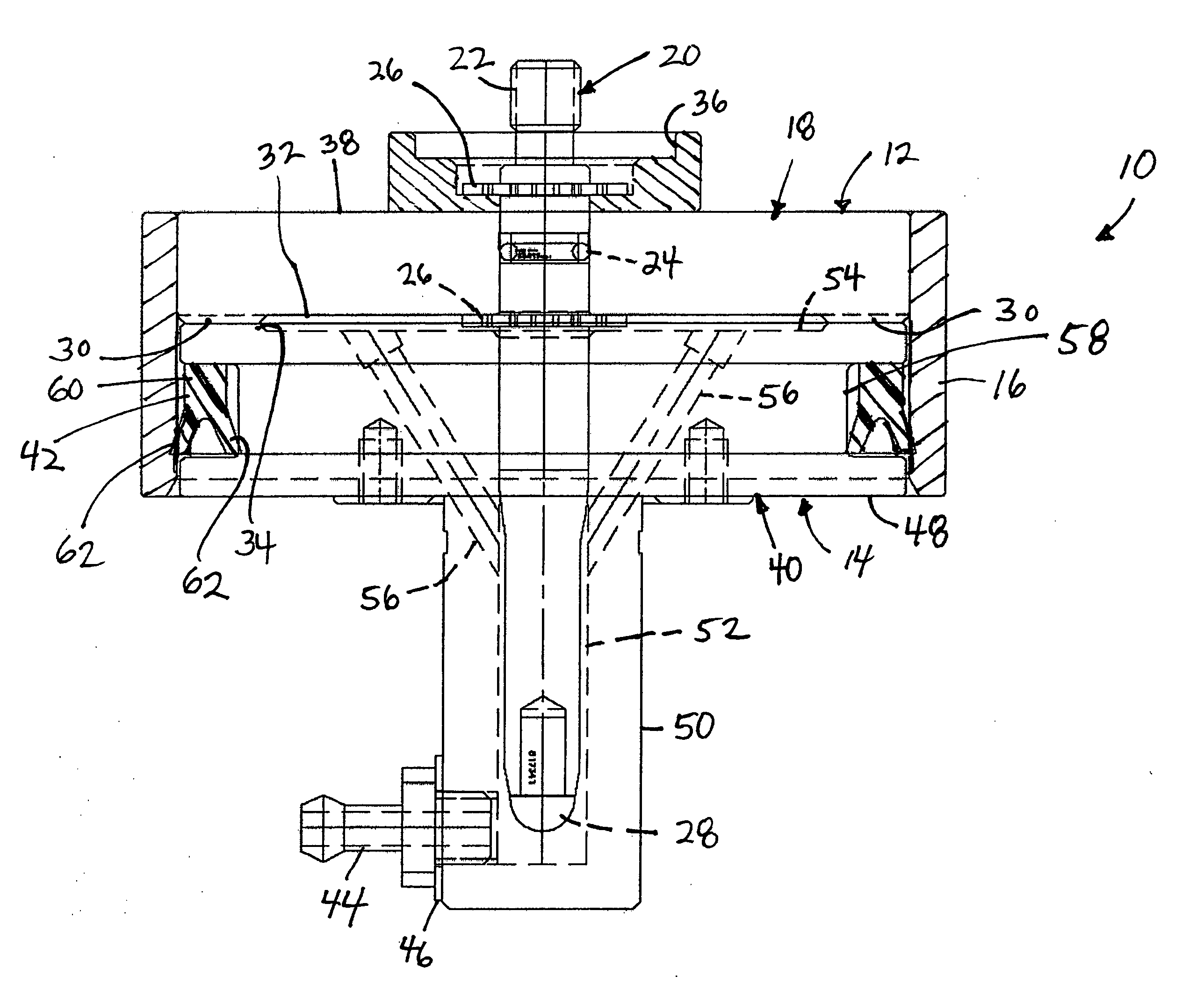
[0051] In an alternative embodiment 300 shown in FIGS. 16 and 17, the head 48 and neck 50 of the bushing do not define two ports that are cross-drilled from the top face 54 to the central bore 52. Instead the assembly 300 has a locating pin 320 defining a central port 324 extending upwardly from a tip of the pin (the pin 320 also includes a threaded portion 322 at a top end for attachment to a headstack). The pin 320 also defines two ports 326 cross drilled to the center port 324. The ports 324, 326 deliver positive and negative air pressure from the barb fitting 44 to the space located between the bushings 18, 40.
embodiment 400
[0052] The wiper seal 42 is received in a circumferential groove 58 in a side wall of the head 48 of the bushing 40 of the fixed locator 14. The wiper seal 42 creates a seal between the side wall of the bushing 40 and an inner surface of the piston ring 16 of the headstack locator 12. In the exemplary embodiment shown, the wiper seal comprises a U-cup wiper seal 42. As shown in FIGS. 3, 6, 7, and 12-14, the U-cup wiper seal 42 has a Y-shaped cross-section including a base portion 60 and two arms 62 extending from the base portion. One of the arms 62 is biased against the circumferential groove 58 of the head 48 of the bushing 40 of the fixed locator 14, while the other arm 62 is biased against the piston ring 16 of the headstack locator 12 when the headstack locator 12 is received over the fixed locator 14. The arms 62 are shaped and adapted to provide an air-tight seal between the headstack locator 12 and the fixed locator 14 when a vacuum is applied to the fixed locator 14 in orde...
PUM
 Abstract
Description
Claims
Application Information