Light reflective and light enhancing tape measure

a technology of reflective tape and light enhancing tape, which is applied in the direction of measuring tapes, movable markers, instruments, etc., can solve the problems of insufficient prior art devices to adequately address these two problems, affecting the reading accuracy of the reflective element, and unable to hold the plastic reflective element. to achieve the effect of easy reading

Inactive Publication Date: 2007-01-25
HOBACK JOHN F +1
View PDF9 Cites 42 Cited by
  • Summary
  • Abstract
  • Description
  • Claims
  • Application Information

AI Technical Summary

Benefits of technology

[0025] An advantage of the present invention is that it provides easy reading in any light condition and ease of use with a rotating beam laser light measuring instrument.

Problems solved by technology

It is awkward to hold the plastic reflective element and measure to it with a tape measure taking time and possibly producing inaccurate readings.
In low light conditions often existing on construction sites prior to installation of the electricity reading a tape measure can be challenging and may require a special light source for the purpose or moving an existing work light to the location of measurement.
None of the prior art devices adequately address these two problems.

Method used


Image

  • Light reflective and light enhancing tape measure
  • Light reflective and light enhancing tape measure
  • Light reflective and light enhancing tape measure

Examples


Embodiment Construction

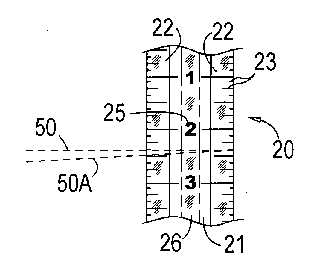
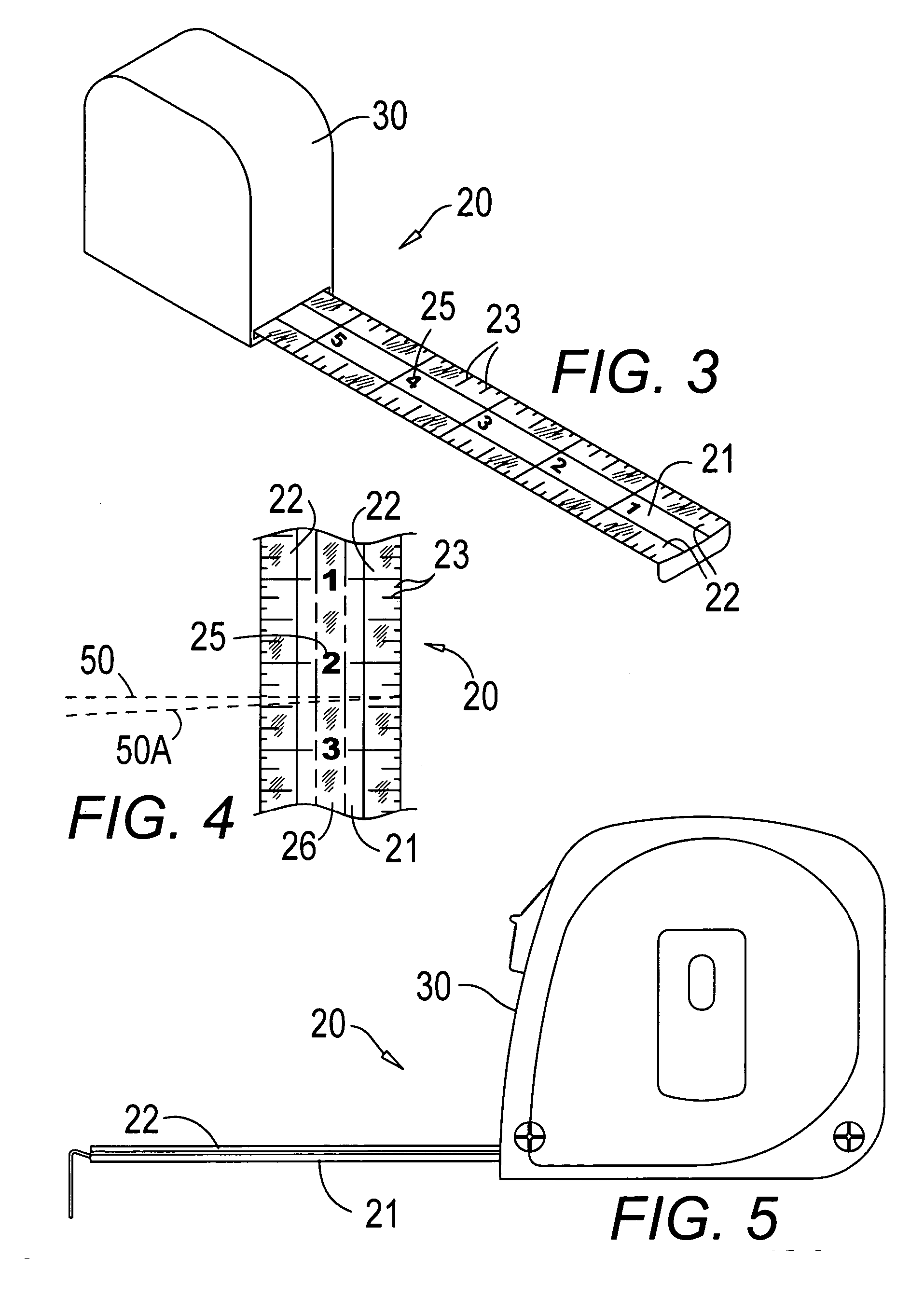
[0031] In FIGS. 1 and 3-5, a light enhanced reflective measuring device 20 is coated for clear readings in various light conditions and for use with rotating laser light equipment 40.

[0032] In FIGS. 3-5, an elongated measuring surface 21, preferably on a retractable tape measure 30, comprises indicia imprinted thereon in a series of spaced lines 23 and related numbers 25 for measuring distances and a pair of spaced light enhancing reflective surfaces 22 attached to the measuring surface over at least a portion of the length of the measuring surface 21 in conjunction with the indicia.

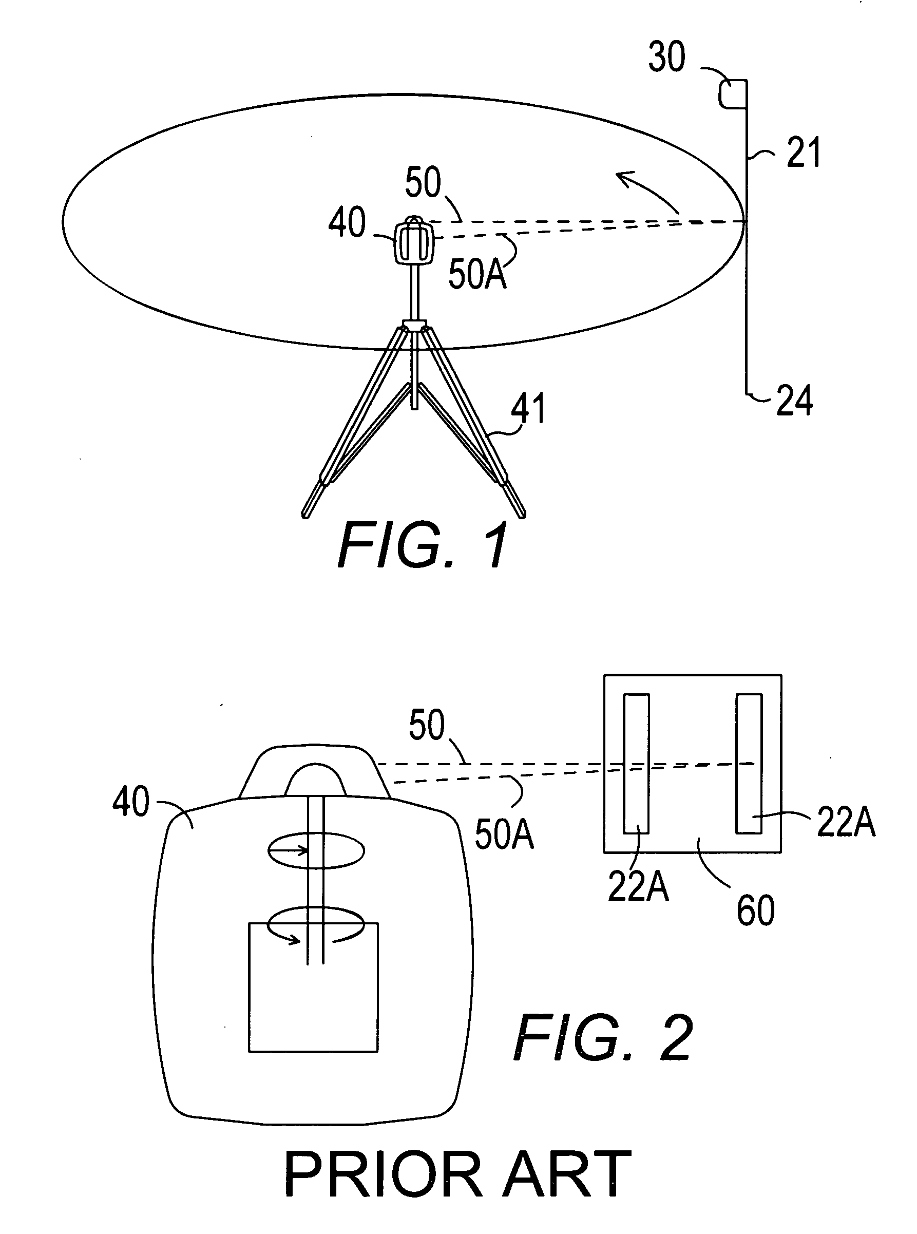
[0033] The spaced light enhancing reflective surfaces 22 have light gathering and reflective qualities, similar to the qualities of reflective road signs and reflective surfaces 22A, in FIG. 2, currently used on a plastic strip 60 in conjunction with a rotating laser instrument 40 to stop the laser beam 50 (reflected back to the instrument in a reflected beam 50A) for measuring a height using a separat...


PUM


Abstract

A tape measure or other measuring surface has an attached pair of light enhancing reflective surfaces in conjunction with the numbers and measurement lines for use with rotating laser light instruments and light enhancement for readability. Reflective and glow in the dark surfaces may also be applied.

Description

BACKGROUND OF THE INVENTION [0001] 1. Field of the Invention [0002] The present invention relates to measuring devices and particularly to a light-reflective and light-enhancing tape measure for reflection of a laser beam, the tape having a light reflective and light-enhancing surface over the distance marks and indicia on the tape. [0003] 2. Description of the Prior Art [0004] Many years ago surveyors used a transit for determining the horizontal or azimuth angles as well as the vertical or elevation angles. A chain or tape measure was used to perform the actual distance measurement between the transit and the point to be established. In addition to this, the surveyor used a telescopic device called a horizontal level and a graduated rod for determining the actual elevation of a point or location in question. [0005] Currently, in the art of surveying a parallel light or energy beam is used to determine a precise distance measurement. This beam can have an infrared or laser energy s...

Claims


Application Information

Patent Timeline
Patent Type & Authority Applications(United States)
IPC IPC(8): G01B3/10G01C15/06
CPCG01B3/1082G01B3/1084G01C15/06G01C15/006G01B2003/1092G01B3/1092G01B3/1003
Inventor HOBACK, JOHN F.HOBACK, JOHNATHAN
Owner HOBACK JOHN F
Why Eureka
Try Eureka