Insert for footwear midsole

Inactive Publication Date: 2007-01-25
ROGUE OUTDOOR BRANDS
View PDF3 Cites 29 Cited by
  • Summary
  • Abstract
  • Description
  • Claims
  • Application Information

AI Technical Summary

Benefits of technology

[0002] The subject invention provides a midsole insert having medial and lateral portions which extend upwardly

Problems solved by technology

However, prior art inserts do little to provide tortional stability since tortional movement of the foot is generally above the top of

Method used


Image

  • Insert for footwear midsole
  • Insert for footwear midsole
  • Insert for footwear midsole

Examples


Embodiment Construction

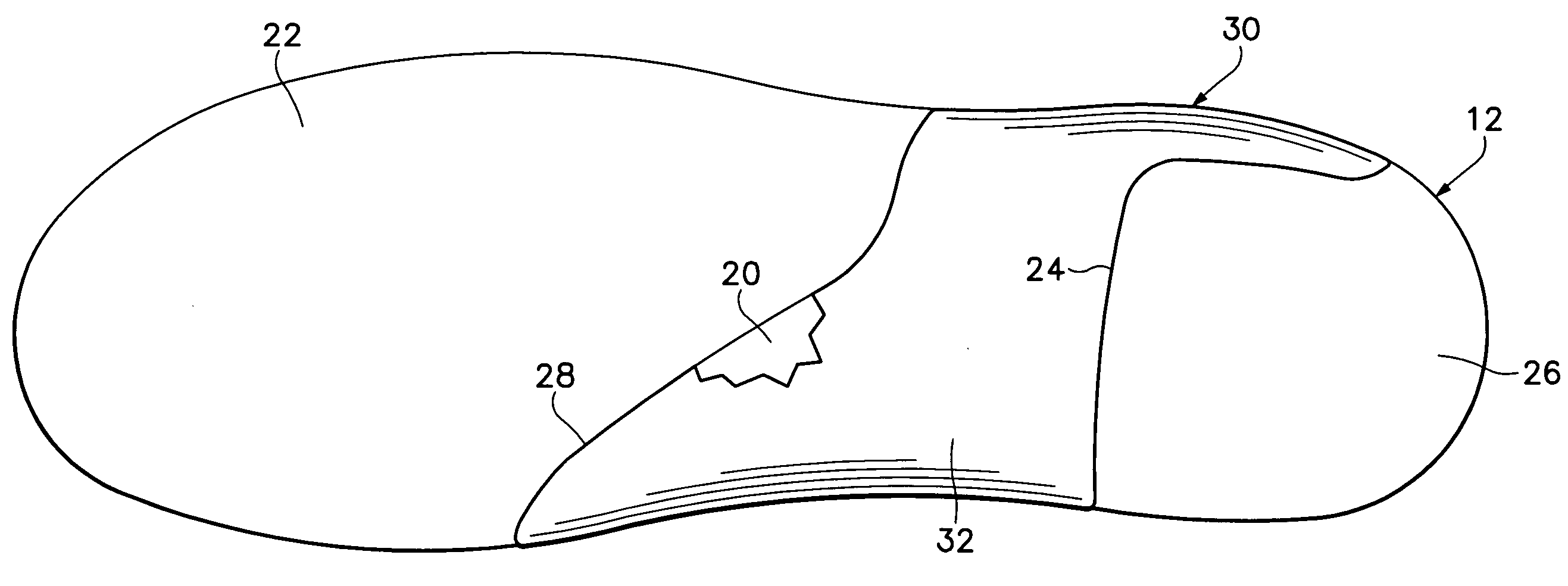
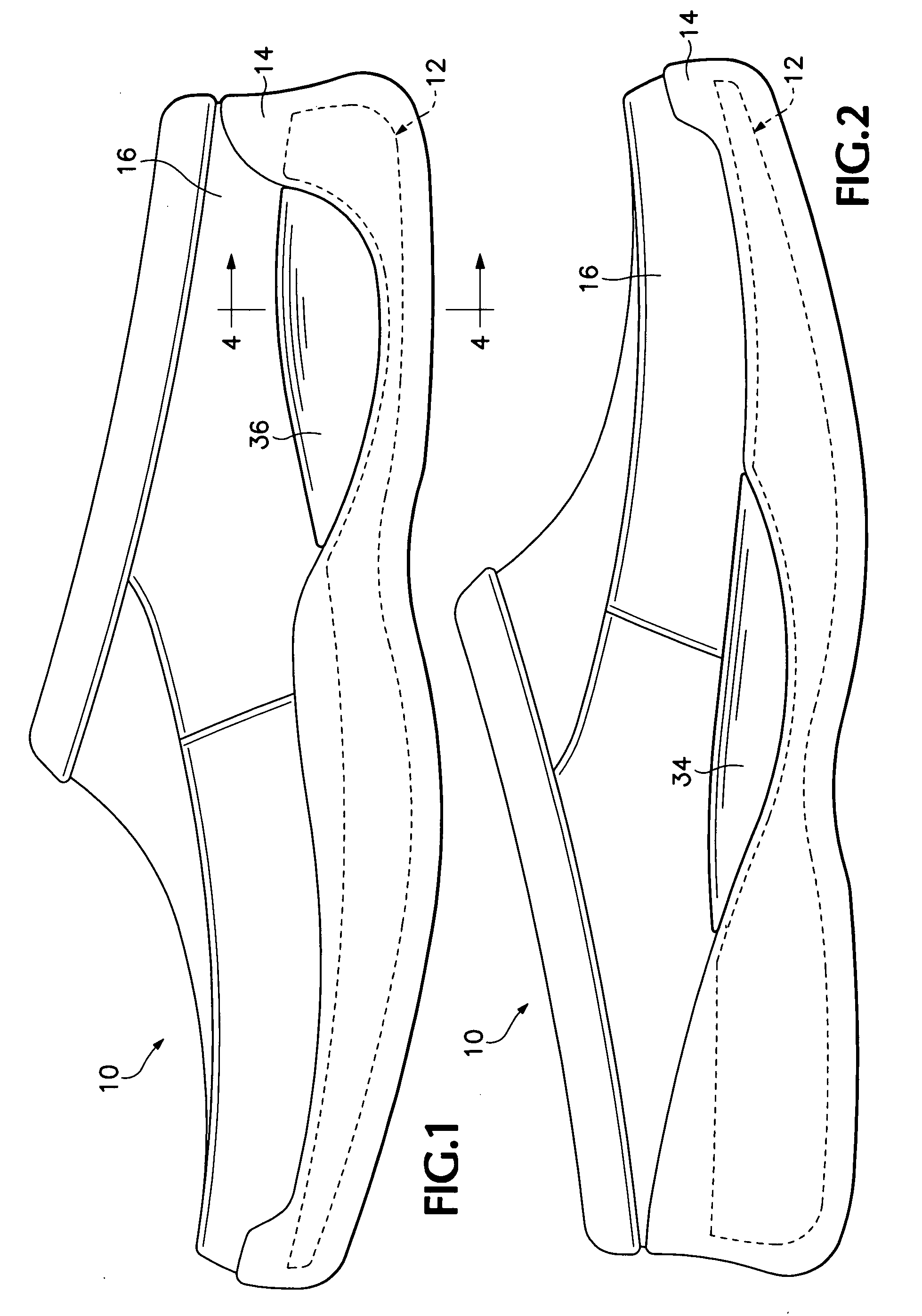
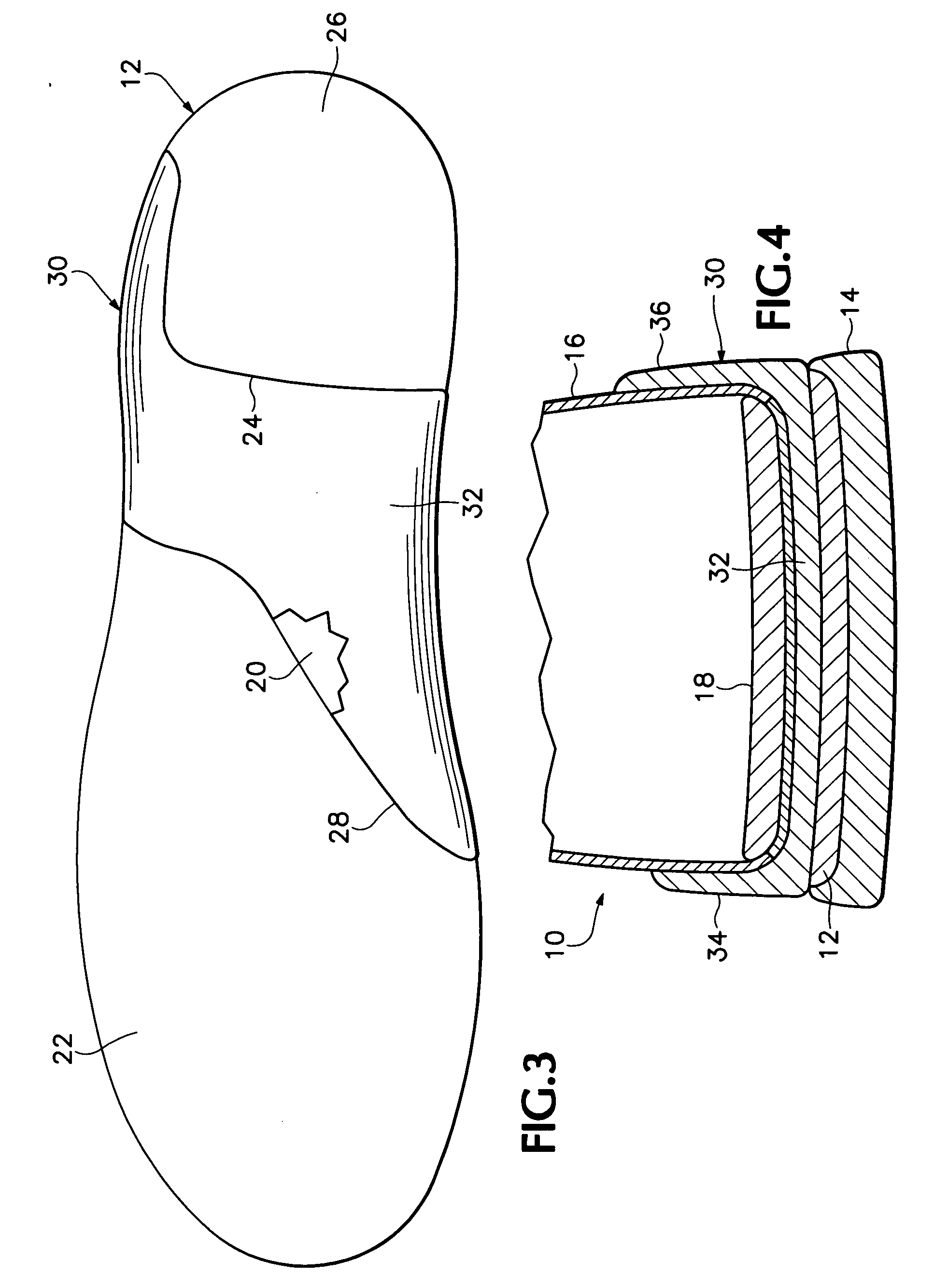
[0008] Referring now to the drawings, a shoe 10 has a midsole 12, an outsole 14 and an upper 16 which are all joined together in the conventional fashion. An inner sole 18 is inserted inside of the shoe above the midsole, FIG. 4. The midsole 12 is made from a material that is flexible and provides good cushioning for the foot. A typical material used for this purpose is molded ethylene vinyl acetate (“EVA”). A cavity 20 is formed in the upper surface 22 and the opposed side surfaces of the insole. Referring to FIG. 3, the back end 24 of the cavity 20 is shown in the embodiment illustrated as extending from the inside edge of the midsole laterally across the midsole proximate the front of the heel 26 and then extending rearwardly to near the back of the heel at the outside edge of the midsole. The front end 28 of the cavity 20 is shown as extending transversely across the midsole from near the ball of the foot at the inside of the midsole to approximately the middle of the arch at th...


PUM


Abstract

An insert for a footwear midsole has a center portion which extends centrally across the midsole, a medial portion which extends upwardly from the center portion at the inner side of the midsole and a lateral portion which extends upwardly from the center portion at the outer side of the midsole. In a preferred embodiment, the insert is made from a cork rubber material and portions of the medial and lateral portions extend above the outsole and overly the upper of the footwear where they are exposed.

Description

BACKGROUND OF THE INVENTION [0001] It is well known to selectively stiffen the sole of footwear by placing a stiffer insert in a portion of the midsole. Doing this provides stability, allows the midsole to bend at the desired location and allows the remainder of the midsole to be made more flexible and cushioning than it otherwise could be. A common material used for such an insert is metal. However, prior art inserts do little to provide tortional stability since tortional movement of the foot is generally above the top of the midsole. In addition, if the insert is metal the portion of the midsole containing the insert is substantially not flexible at all. Finally, if the insert is metal, it activates airport metal dectors if the user forgets to remove the footwear before passing through them. BRIEF SUMMARY OF THE INVENTION [0002] The subject invention provides a midsole insert having medial and lateral portions which extend upwardly from a center portion which provides both longit...

Claims


Application Information

Patent Timeline
IPC IPC(8): A43B13/38
CPCA43B7/1495A43B13/125A43B13/12A43B7/24
Inventor SCOFIELD, ROBERTEARLE, JOHNDAHLSTEN, JANELLE
Owner ROGUE OUTDOOR BRANDS
Why Eureka
Try Eureka