
Tone generator control apparatus and program for electronic wind instrument

a control apparatus and electronic wind instrument technology, applied in the direction of instruments, electrophonic musical instruments, selection arrangements, etc., can solve the problems of not being able to acquire such a real tone generating frequency, not being able to execute a performance, and not being able to permit different playing styles to properly play different octaves

Inactive Publication Date: 2007-01-25
YAMAHA CORP
View PDF36 Cites 23 Cited by
  • Summary
  • Abstract
  • Description
  • Claims
  • Application Information

AI Technical Summary

Benefits of technology

[0016] In view of the foregoing, it is an object of the present invention to provide a novel tone generator control apparatus for an electronic wind instrument which can readily simulate octave-specific playing styles of an air-lead instrument.
[0020] According to the present invention, the jet parameter is calculated using the frequency of the tone signal to be generated in correspondence with the detected fingering state, and thus, there is no need to acquire an actual tone generating frequency. Further, during generation of a tone signal of a predetermined octave, the tone generating octave is raised by one octave once it is detected that the calculated jet parameter has decreased to the first predetermined value; thus, after a user or human player plays in such a manner that the jet parameter reaches the first predetermined value, a tone signal higher in pitch by one octave can be generated with the user keeping the same playing (i.e., air-blowing) state, so that particular playing (i.e., air-blowing) operation for increasing the jet traveling angle from π / 2 to π is not required. Further, during generation of the tone signal having been raised in pitch by one octave, the tone generating octave is lowered by one octave once it is detected that the calculated jet parameter has increased to the second predetermined value greater than the first predetermined value; thus, after the user or human player plays in such a manner that the jet parameter reaches the second predetermined value, a tone signal lower in pitch by one octave can be generated with the user keeping the same playing (i.e., air-blowing) state, so that particular playing (i.e., air-blowing) operation for decreasing the jet traveling angle from 3π / 2 to 3π / 4 is not required. In this way, the present invention can readily perform octave-specific playing styles. Further, the present invention imparts a hysteresis characteristic to the octave switching by setting the second predetermined value greater than the first predetermined value. Therefore, no octave change occurs as the human player plays in such a manner as to slightly change the pitch as long as the change is within a range where the jet parameter does not reach the first predetermined value (when the pitch is to be raised by one octave) or within a range where the jet parameter does not reach the second predetermined value (when the pitch is to be lowered by one octave); thus, the present invention permits various rendition styles, such as a pitch bend and vibrato. As a result, the tone generator control apparatus according to the first aspect of the present invention can properly deal with embouchures of various flute-performing methods and therefore suits users who want to enjoy playing that is close to playing of a flute.
[0022] The tone generator control apparatus according to the first aspect of the invention may further comprise: a fourth control section that, during generation, by the tone generator section, of the tone signal of the predetermined octave, controls the tone generator section to gradually raise the frequency of the tone signal as the jet parameter calculated by the calculation section decreases toward the first predetermined value, and a fifth control section that, during generation, by the tone generator section, of the tone signal of the pitch having been raised by one octave, controls the tone generator section to gradually raise the frequency of the tone signal as the jet parameter calculated by the calculation section increases toward the second predetermined value. With such arrangements, it is possible to simulate slow variation in tone generating frequency before and after an octave change in an actual air-lead instrument. Thus, the user or human player can feel a sign of an octave change and thereby smoothly perform octave-specific playing.
[0025] Namely, in the tone generator control apparatus according to the second aspect of the present invention, once the distance between the jet blowout outlet and the edge has decreased to the predetermined value during generation, by the tone generator section, of the tone signal of the predetermined octave, the tone generating octave is raised by one octave, while, once the distance between the jet blowout outlet and the edge has increased above the predetermined value during generation, by the tone generator section, of the tone signal having been raised in pitch by one octave, the tone generating octave is lowered by one octave. Thus, the present invention permits octave-specific playing by only changing the lip-to-edge distance and therefore is very suitable for beginners. With the above-described tone generator control apparatus according to the first aspect of the invention, the user is allowed to enjoy playing close to playing of a flute; however, it is difficult to execute a performance in great tone volume in a low pitch range because there is a tendency that no tone is generated unless the jet flow velocity is reduced, and it is difficult to execute a performance in small tone volume in a high pitch range because there is a tendency that no tone is generated unless the jet flow velocity is increased. However, with the above-described tone generator control apparatus according to the second aspect of the present invention, where the octave-switching control is performed using the distance between the jet blowout outlet and the edge rather than the jet parameter, such as the jet traveling angle, it is possible to execute not only a performance in great volume in a low pitch range but also a performance in small tone volume in a high pitch range.
[0027] With the octave-switching control performed on the basis of the current tone generating state and jet parameter as stated above, the tone generator control apparatus of the present invention can accomplish the advantageous benefit that octave-specific playing styles of an air-lead instrument, such as a flute, can be appropriately simulated with an utmost ease. Further, with the octave-switching control performed on the basis of the current tone generating state and jet-blowout-outlet-to-edge distance as stated above, the tone generator control apparatus of the present invention advantageously permits not only octave-specific playing but also a performance in great volume in a low pitch range and a performance in small volume in a high pitch range, by only changing the lip-to-edge distance.

Problems solved by technology

With the thus-constructed electronic musical instrument, it is not possible to execute a performance in accordance with blowing inputs to the mouse piece.
The electronic musical instruments disclosed in Patent Literature 2 to Patent Literature 5, on the other hand, are capable of executing a performance in accordance with blowing inputs, but they do not permit different playing styles to properly play different octaves (i.e., “octave-specific playing styles”) as played with an ordinary flute or other air-lead instrument.
It would be conceivable to permit different playing styles to properly play different octaves (octave-specific playing styles) by applying the information and technique disclosed in Non-patent literature 1; however, in the case where the information and technique disclosed in Non-patent literature 1 is applied as-is, the following problems would be encountered.
However, because the electronic musical instruments are not natural musical instruments. it is not possible to acquire such an actual tone generating frequency.
(2) In order to obtain a jet transfer time τe with a high accuracy, it is necessary to sense a jet flow velocity at a number of points; however, it is practically difficult to position a number of flow velocity sensors along a jet flow path.

Method used


Image

  • Tone generator control apparatus and program for electronic wind instrument
  • Tone generator control apparatus and program for electronic wind instrument
  • Tone generator control apparatus and program for electronic wind instrument

Examples


Embodiment Construction

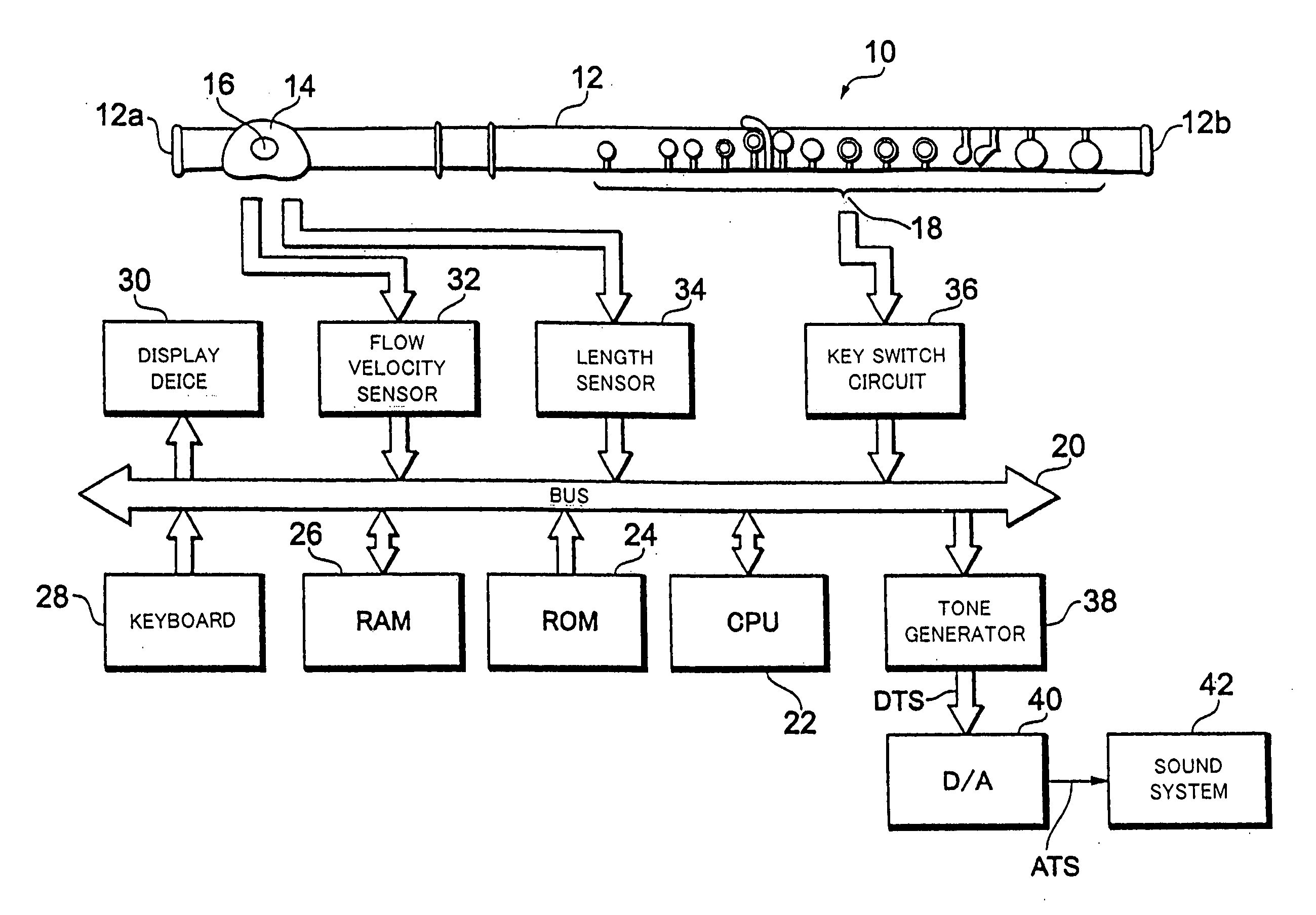
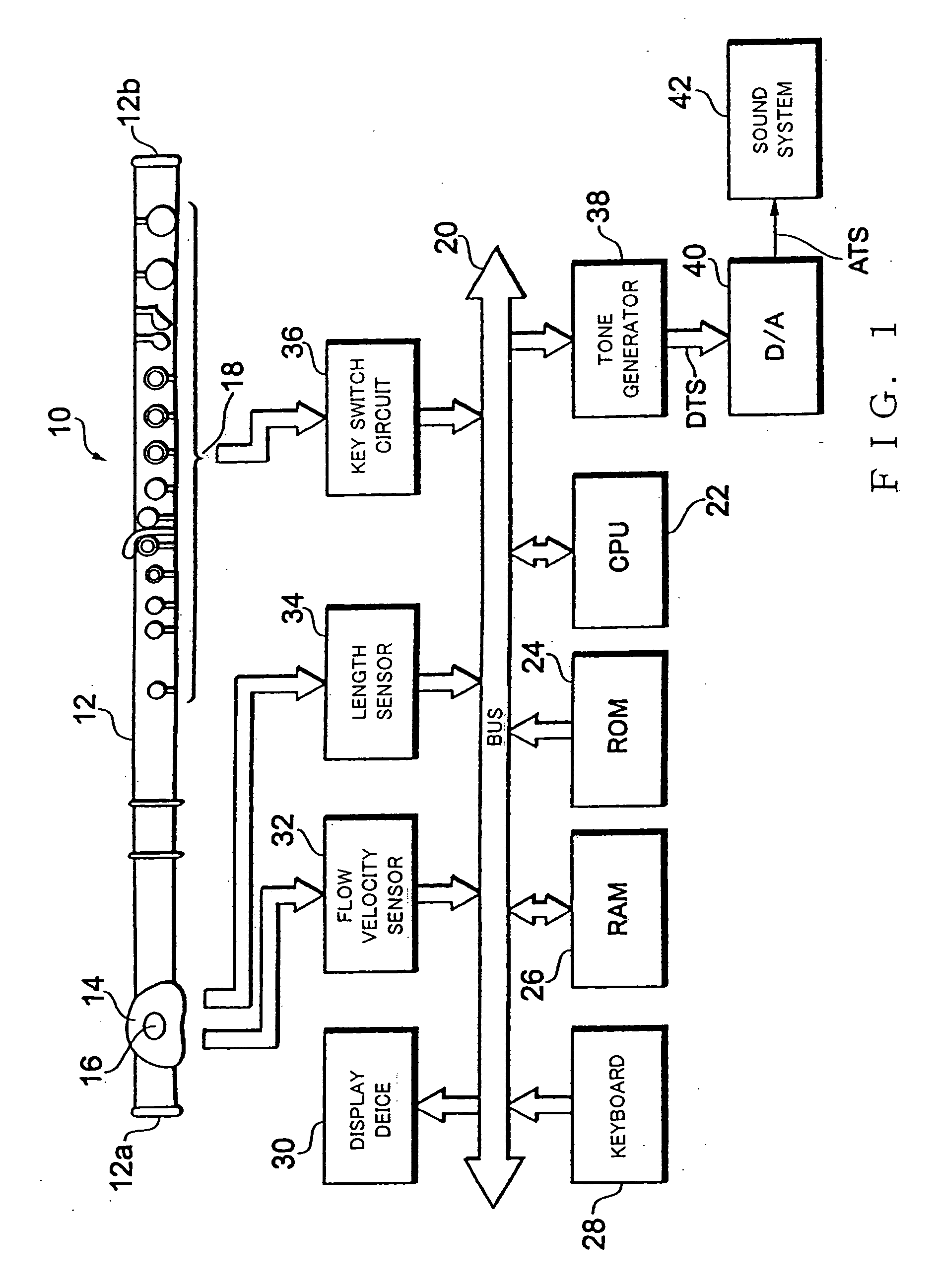
[0056]FIG. 1 is a block diagram showing an example circuit construction of an electronic wind instrument in accordance with an embodiment of the present invention, where tone generator control is performed using a small-sized computer.

[0057] Wind controller 10, similar in shape to a flute, includes a tubular body section 12 having an elongated cavity extending from a closed end 12a to an open end 12b. On an outer peripheral surface of the tubular body section 12, there are provided a lip plate 14 having a blow hole or embouchure hole 16 communicating with the cavity of the tubular body section 12, and a tone key group 18 including a plurality of pitch-designating tone keys. The wind controller 10 does not generate a tone per se as a flute does, and thus, any suitable size of the tubular body section 12 may be set with user's usability etc. taken into account. The closed end 12a may be replaced with an open end.

[0058] The lip plate 14 has attached thereto a flow velocity sensor for...


PUM


Abstract

Flow velocity sensor and a length sensor are provided on or near an edge of the lip plate which the air jet from the embouchure hole impinges against. Jet flow velocity Ue at the edge and a jet-blowout-outlet-to-edge distance d are detected by the sensors. Jet transfer time τe is calculated by an equation of τe=d / Ue, and a jet traveling angle θe′ is calculated by an equation of θe′=2πfso1×τe (where fso1 represents a frequency of a tone to be generated). When θe′ has decreased to π / 2 during tone generation in a primary mode, the mode changes to a secondary mode to raise the pitch of the currently generated tone by one octave. When θe′ has increased to 3π / 4 during tone generation in the secondary mode, the mode changes to the primary mode to lower the pitch of the currently generated tone by one octave.

Description

BACKGROUND OF THE INVENTION [0001] The present invention relates to a tone generator control apparatus and program suited for application to electronic wind instruments. [0002] Generally, with air-lead musical instruments, such as flutes and piccolos, there has been employed so-called “octave-specific playing” for properly playing two different tones, having a same pitch name but different in octave with a same fingering pattern or state. In FIG. 22, there are shown a fingering pattern or state for generating or sounding notes “E” of first and second octaves (indicated by A in the figure), and a fingering state for sounding notes “F” of the first and second octaves (indicated by B in the figure). For example, when notes “E” of the first and second octaves are to be generated with the fingering state shown in FIG. 22, a human player blows air relatively weakly for the E note of the first octave but blows air relatively strongly for the E note of the second octave. Embouchure too slig...

Claims


Application Information

Patent Timeline
IPC IPC(8): G10H1/00
CPCG10H1/053G10H5/007G10H2250/515G10H2250/461G10H2220/361
Inventor MASUDA, HIDEYUKI
Owner YAMAHA CORP
Learn More