Marine vessel maneuvering supporting apparatus, marine vessel including the marine vessel maneuvering supporting apparatus, and marine vessel maneuvering supporting method

a technology for supporting apparatus and marine vessels, which is applied in the direction of instruments, special purpose vessels, vessel construction, etc., can solve the problems of increasing fuel consumption, increasing the drag of the hull, and increasing the cost of the vessel, so as to facilitate the maneuvering operation of the stationary marine vessel

Inactive Publication Date: 2007-01-25
YAMAHA MOTOR CO LTD
View PDF10 Cites 63 Cited by
  • Summary
  • Abstract
  • Description
  • Claims
  • Application Information

AI Technical Summary

Benefits of technology

[0013] To overcome the problems described above, preferred embodiments of the present invention provide marine vessel...

Problems solved by technology

However, small-scale marine vessels, such as cruisers, rarely include side thrusters because side thrusters cause various problems, such as an increase in costs, a need to modify the design of the hull to allow for installation of the side thrusters, and an increase in fuel consumption due to an increase in drag of the hull.
However, the lateral maneuvering of the small-scale marine vessels having no side thruster is very difficult, thereby requiring skilled operation of the marine vessel.
However, the marine vessel maneuvering apparatus is n...

Method used


Image

  • Marine vessel maneuvering supporting apparatus, marine vessel including the marine vessel maneuvering supporting apparatus, and marine vessel maneuvering supporting method
  • Marine vessel maneuvering supporting apparatus, marine vessel including the marine vessel maneuvering supporting apparatus, and marine vessel maneuvering supporting method
  • Marine vessel maneuvering supporting apparatus, marine vessel including the marine vessel maneuvering supporting apparatus, and marine vessel maneuvering supporting method

Examples


Embodiment Construction

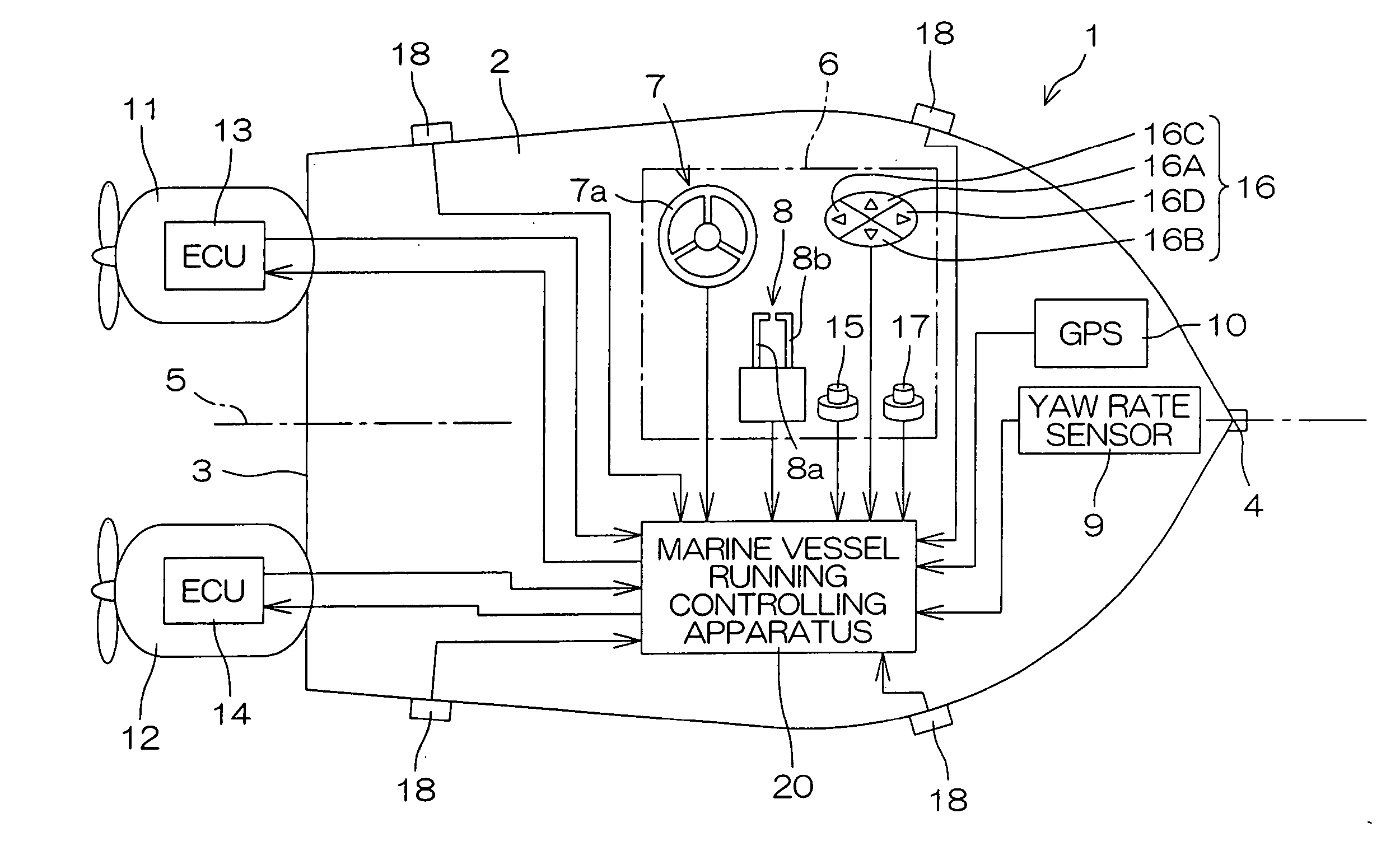
[0077]FIG. 1 is a schematic diagram illustrating a marine vessel 1 according to one preferred embodiment of the present invention. The marine vessel 1 is preferably a relatively small-scale marine vessel, such as a cruiser or a boat, and includes a pair of outboard motors 11, 12 attached to a stern (transom) 3 of a hull 2. The outboard motors 11, 12 are positioned laterally symmetrically with respect to a center line 5 of the hull 2 extending through the stern 3 and a stem 4 of the hull 2. That is, the outboard motor 11 is attached to a rear port-side portion of the hull 2, while the outboard motor 12 is attached to a rear starboard-side portion of the hull 2. The outboard motor 11 and the outboard motor 12 will hereinafter be referred to as “port-side outboard motor 11” and “starboard-side outboard motor 12”, respectively, to differentiate therebetween. Electronic control units 13 and 14 (hereinafter referred to as “outboard motor ECU 13” and “outboard motor ECU 14”, respectively) ...


PUM


Abstract

A marine vessel maneuvering supporting apparatus performs a stationary marine vessel maneuvering support operation, the marine vessel including a pair of propulsion systems which respectively generate propulsive forces on a rear port side and a rear starboard side of a hull, and a pair of steering mechanisms which respectively change steering angles. The apparatus includes a position detecting section which detects a position of the marine vessel, a marine vessel maneuvering support starting command section, a marine vessel maneuvering support starting position storing section, a steering controlling section which controls the steering angles of the respective steering mechanisms such that the marine vessel has a turning angular speed of zero in response to the marine vessel maneuvering support starting command, a target propulsive force calculating section which calculates target propulsive forces to be generated from the respective propulsion systems, such that at least one of x- and y-coordinates of the current marine vessel position is maintained substantially equal to a corresponding one of x- and y-coordinates of the marine vessel maneuvering support starting position, and a propulsive force controlling section which controls the propulsion systems to attain the target propulsive forces.

Description

BACKGROUND OF THE INVENTION [0001] 1. Field of the Invention [0002] The present invention relates to a marine vessel maneuvering supporting apparatus which is applicable to a marine vessel having at least one pair of propulsion systems provided at a stern thereof, a marine vessel including the marine vessel maneuvering supporting apparatus, and a marine vessel maneuvering supporting method. [0003] 2. Description of the Related Art [0004] When a marine vessel travels toward or away from a wharf, a lateral maneuvering operation is performed to laterally move the hull of the marine vessel with the angular speed (stem turning speed) of the hull being maintained constant (for example, at zero). In general, large-scale marine vessels include a plurality of small propulsion systems called “side thrusters” provided at a stem and other locations of a hull to laterally move the hull. The side thrusters each generate a propulsive force in a lateral direction of the hull. Thus, the hull can be ...

Claims


Application Information

Patent Timeline
IPC IPC(8): B63H25/00B63B35/70B63H25/42B63J99/00
CPCB63J99/00B63H25/42B63H2020/003B63H2025/026G05D1/0208
Inventor KAJI, HIROTAKASUEMORI, MASARU
Owner YAMAHA MOTOR CO LTD
Why Eureka
Try Eureka