Sheet metal pipe geometry for minimum pressure drop in a heat exchanger

a heat exchanger and sheet metal pipe technology, applied in the direction of heat exchanger casings, heat exchange apparatus, light and heating equipment, etc., can solve the problems of increasing fluid pressure loss through the tube, erosion and damage, and further compounding of problems, so as to reduce turbulence and pressure loss, reduce cooling pressure drop, and reduce turbulence and damage

Inactive Publication Date: 2007-01-25
DELPHI TECH INC
View PDF9 Cites 19 Cited by
  • Summary
  • Abstract
  • Description
  • Claims
  • Application Information

AI Technical Summary

Benefits of technology

[0010] The subject invention provides a radiator header tank to pipe joint that reduces coolant pressure drop by reducing turning losses at the transition between the pipe and the header tank wall.
[0011] The heat exchanger assembly of the subject invention is distinguished by a transition between the header wall and the pipe extending transition completely around the opening to present an expanding flow control surface between from the header wall to the pipe for conveying the heat exchange medium closely over the control surface between the tank interior and the pipe to reduce turbulence and pressure loss at the transition between the tank interior the said pipe.
[0012] This invention provides a transition to significantly reduce the oil cooler pressure drop penalty and / or reduce the size of the tank. A method of determining the required feature size and practical designs are provided for integrally molded or fabricated sheet metal tanks. Several configurations are shown that incorporate an internal radius or chamfer to eliminate the pipe extension inside the tank.

Problems solved by technology

However, a thinner flow tube creates more fluid pressure loss through the tube, end to end.
One source of coolant pressure drop through the heat exchanger that has not received a great deal of attention in the prior art is turbulence or “turning” losses that occur at the transition between the pipe opening and the enclosed interior of the header tank.
The other liquid medium heat exchanger typically found in an automobile, the heater core, has a similar cross flow configuration, but faces a different problem.
However, the fact that the ends of the nearest tubes are in line with the inlet pipe is a detriment, because the force of the impinging flow against the near tube ends causes erosion and damage.
This problem is further compounded when internal oil coolers or baffles are required that partially block the inlet / outlet pipes.
Due to packaging constraints, it is common for oil coolers to straddle the coolant inlet / outlet pipes.
This flow blockage increases coolant pressure drop and creates local regions of high coolant velocity that can cause erosion corrosion of the oil cooler.
Typically it is not practical to reduce the pressure drop penalty below the levels described above because the increased stand off height required will reduce the size of oil cooler that can be installed in the tank, or a larger tank must be used with increased packaging space, mass, and cost penalties.

Method used


Image

  • Sheet metal pipe geometry for minimum pressure drop in a heat exchanger
  • Sheet metal pipe geometry for minimum pressure drop in a heat exchanger
  • Sheet metal pipe geometry for minimum pressure drop in a heat exchanger

Examples


Embodiment Construction

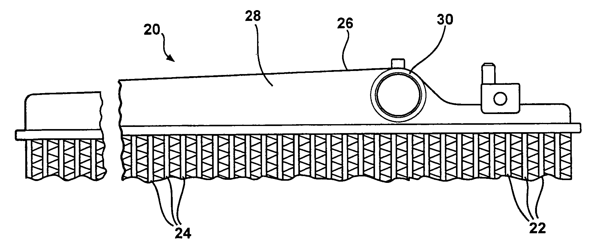
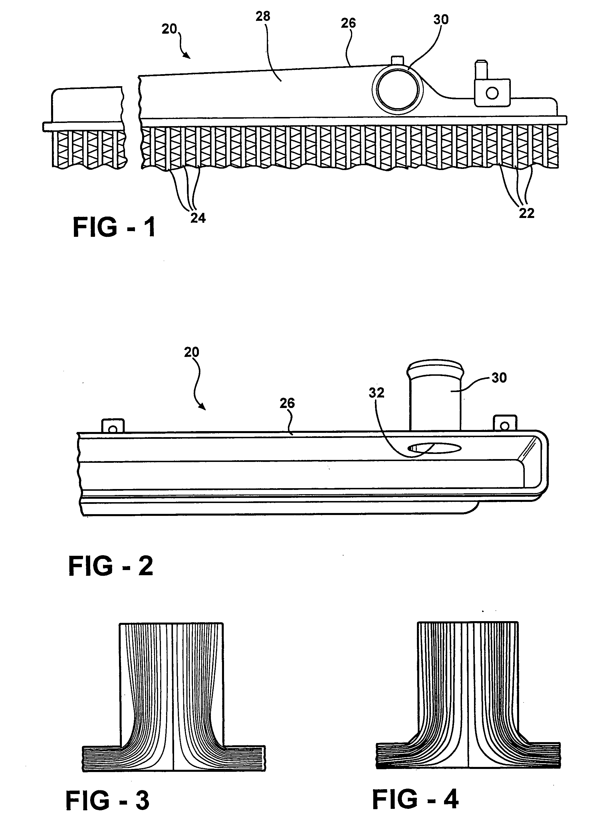
[0025] A heat exchanger assembly constructed in accordance with the subject invention is generally shown at 20 in FIGS. 1 and 2. The assembly 20 includes a core comprising a plurality of flow tubes 22 having heat exchange fins 24 extending therebetween. A header tank 26 distributes a flowing liquid heat exchange medium to and from the flow tubes 22 and presents a header wall 28 with an interior surface. A pipe 30 is disposed in an opening through the header wall 28.

[0026] A joint extends between the pipe 30 and the header wall 28 to define an endless transition completely around the opening to present an expanding flow control surface between the pipe 30 and the interior surface 32 of the header wall 28 for conveying the heat exchange medium closely over the control surface between the interior surface and the pipe 30 to reduce turbulence and pressure loss at the transition between the interior surface and the pipe 30.

[0027] A typical pipe to header wall joint is shown in FIG. 3 w...


PUM

PropertyMeasurementUnit
radiusaaaaaaaaaa
chamfer angleaaaaaaaaaa
pressure lossaaaaaaaaaa

Abstract

A heat exchanger joint between a pipe and a header wall defines an endless transition for conveying the heat exchange medium closely over a control surface of a radius or a chamfer between the interior surface and the pipe to reduce turbulence and pressure loss. The radiused or chamfered flow control surface expands radially as it opens axially into the interior surface of the header wall.

Description

FIELD OF THE INVENTION [0001] This invention relates to automotive heat exchangers in general, and specifically to a liquid flow heat exchanger, such as a radiator, with a novel in tank structure for reducing the pressure drop caused by flow turning losses. BACKGROUND OF THE INVENTION [0002] Automotive heat exchangers that use a pumped, liquid heat exchange medium, as opposed to a compressed gaseous / liquid heat exchange medium, include radiators and heaters. Typically, these include two elongated manifolds or header tanks, one on each side of the heat exchanger, with a central core consisting of a plurality of evenly spaced, flattened flow tubes and interleaved corrugated air fins running between the two tanks. Each tank is generally box shaped, with parallel side walls, a back wall joining the side walls, two axially opposed ends, and an open area opposite the back wall, which is eventually closed off when it is fixed leak tight to one side of the core. Each header tank distributes...

Claims


Application Information

Patent Timeline
Patent Type & Authority Applications(United States)
IPC IPC(8): F28F9/02
CPCF28F9/0234F28F21/067F28F9/0246
Inventor BEAMER, HENRY EARLCALHOUN, CHRIS A.EL MOUTAMID, KHALIDHUANG, LIN-JIE
Owner DELPHI TECH INC
Why Eureka
Try Eureka