
High voltage proximity warning system utilizing wireless sensors and method

a wireless sensor and proximity warning technology, applied in the direction of load-engaging elements, antennas, antenna adaptation in movable bodies, etc., can solve the problems of single wire device, unsuitable for use on insulated boom trucks such as insulated man-lifts and bucket trucks, and clear unacceptable for a new generation of cranes and equipment that utilize articulated booms

Inactive Publication Date: 2007-01-25
NICKERSON IRVIN
View PDF19 Cites 23 Cited by
  • Summary
  • Abstract
  • Description
  • Claims
  • Application Information

AI Technical Summary

Benefits of technology

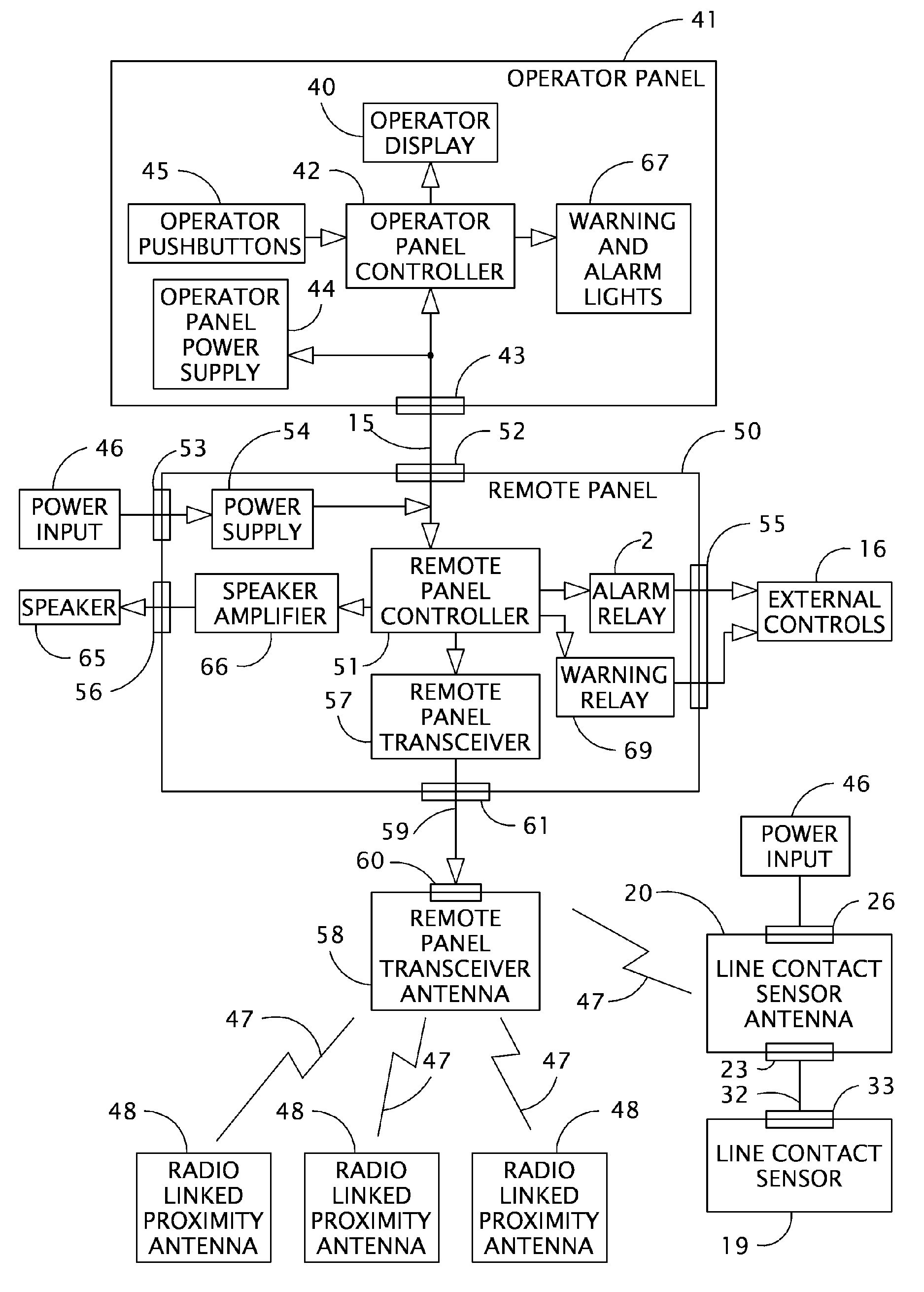
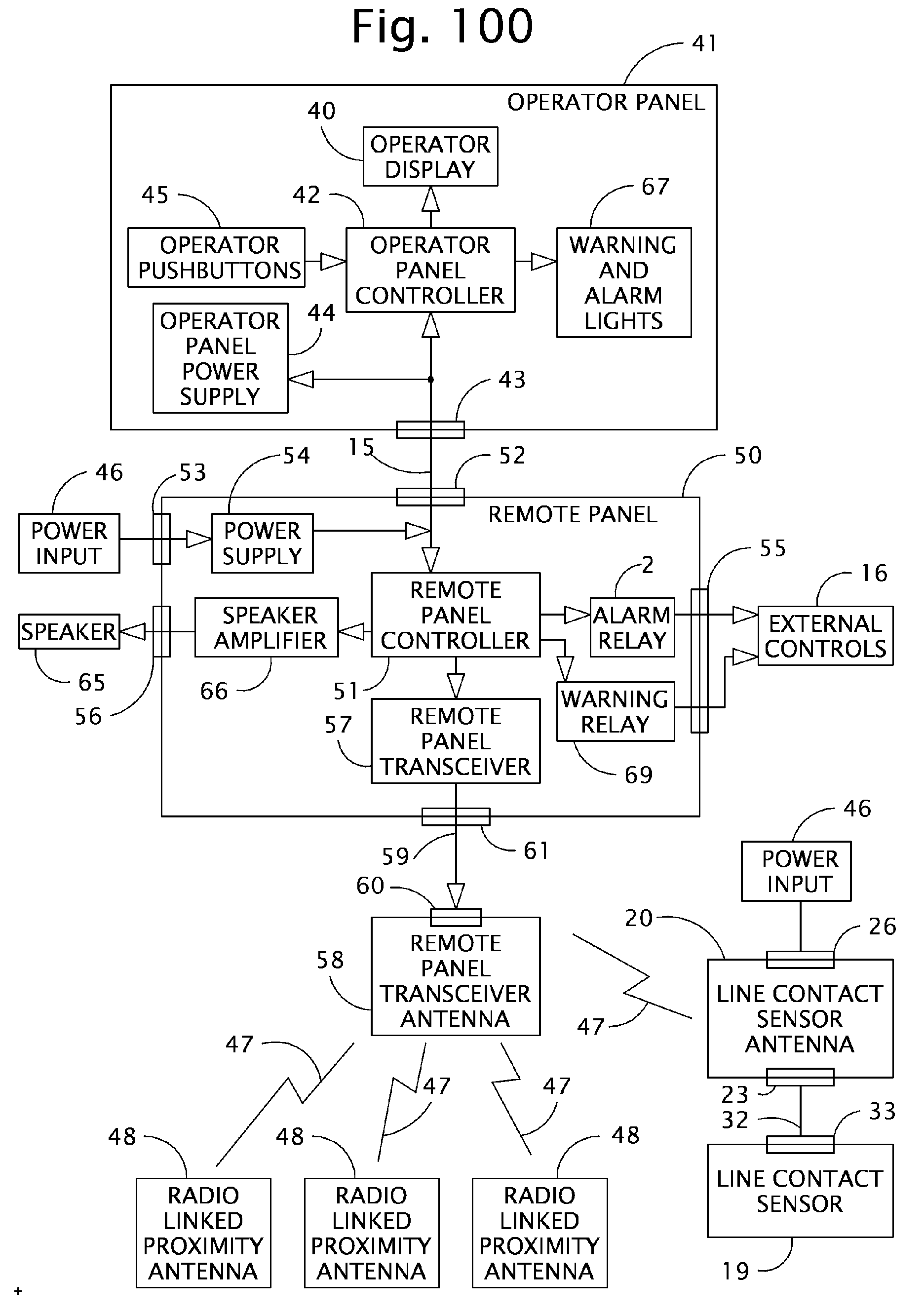
"The invention is a high voltage proximity warning system for heavy equipment that uses wireless sensors and a control panel to detect the presence of high voltage lines. The system includes multiple radio linked proximity antennas strategically positioned on the heavy equipment to avoid electric field shadowing. The system provides a convenient and effective way for operators to work close to high voltage lines without risking damage or injury. The control panel is located in the cab of the heavy equipment and includes an operator display, pushbuttons, and data terminals for connection to a remote panel or multiple control panels. The system can be used with various types of heavy equipment and can help prevent accidents and damage caused by high voltage lines."

Problems solved by technology

This type of device is sufficient for use on heavy equipment such as boom cranes that utilize straight booms, but is clearly unacceptable for a new generation of cranes and equipment that utilize articulated booms.
It is also unsuitable for use on insulated boom trucks such as insulated man-lifts and bucket trucks.
A study conducted by the Bureau of Mines on Feb. 22, 1980 entitled “Evaluation of Proximity Warning Devices” discounts single wire devices as being unreliable due to the characteristic shadowing of the antenna by the crane boom which diminishes, and often disables its ability to detect the high voltage lines.

Method used


Image

  • High voltage proximity warning system utilizing wireless sensors and method
  • High voltage proximity warning system utilizing wireless sensors and method
  • High voltage proximity warning system utilizing wireless sensors and method

Examples


Embodiment Construction

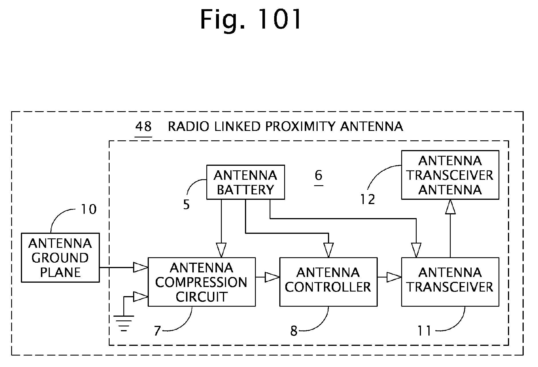
[0031] Listed numerically below with reference to the drawings and terms used to describe features of this invention. These terms and numbers assigned to them designate the same features throughout this description. [0032]1 Alarm light [0033]2 Alarm relay [0034]3 Alarm setpoint [0035]4 Antenna base [0036]5 Antenna battery [0037]6 Antenna circuit board [0038]7 Antenna compression circuit [0039]8 Antenna controller [0040]9 Antenna cover [0041]10 Antenna ground plane [0042]11 Antenna transceiver [0043]12 Antenna transceiver antenna [0044]13 Circuit board screw [0045]14 Cover screw [0046]15 Data and power connector cable [0047]16 External controls [0048]17 Heavy equipment [0049]18 High voltage lines [0050]19 Line contact sensor [0051]20 Line contact sensor antenna [0052]21 Line contact sensor antenna base [0053]22 Line contact sensor antenna circuit board [0054]23 Line contact sensor antenna communications connector [0055]24 Line contact sensor antenna controller [0056]25 Line contact s...


PUM


Abstract

A high voltage proximity warning system utilizing wireless sensors for preventing heavy equipment from contacting high voltage lines is provided. The warning system is adapted for use with mobile heavy equipment that can be used around overhead power transmission lines. The alarm system consists of a number of wireless radio linked proximity antennas mounted on heavy equipment in locations that could possibly come into contact with high voltage lines. These wireless antennas detect the electric field in the proximity of the high voltage lines and transmits signals to a control panel located in the proximity of the operator of the equipment. The resulting signal level is displayed on the control panel along with an alarm setpoint. If the signal level rises above the alarm setpoint, the control panel provides a visual alarm indication, an audio alarm annunciation, and control signals that can directly inhibit specific functions of the heavy equipment.

Description

CROSS-REFERENCED TO RELATED APPLICATION [0001] This Application claims the benefit of U.S. Provisional Application Ser. No. 60 / 630,012, filed Nov. 22, 2004.BACKGROUND OF THE INVENTION [0002] This invention relates to warning devices for proximity of vehicles including heavy equipment, television trucks or any other vehicle that may come into contact with a high-voltage power lines avoiding dangerous and damaging contact. [0003] There are known sensors of proximity of vehicles to high-voltage power lines, but none with the high sensitivity, precision of detection, flexibility, and extensive protective coverage to equipment operators of heavy equipment taught by this invention. [0004] Dangerous and damaging contact of high-voltage power lines by vehicles continues to be a problem to equipment operators, to their rescuers, to affected users of electricity, to power companies, to construction companies and to other users of the vehicles. [0005] Examples of most-closely related known but...

Claims


Application Information

Patent Timeline
Patent Type & Authority Applications(United States)
IPC IPC(8): G08B21/00
CPCH01Q1/002B66C15/065
Inventor NICKERSON, IRVIN
Owner NICKERSON IRVIN
Learn More