Shocking device having a time-based monitoring and recording circuit

a time-based monitoring and recording circuit technology, applied in the field of shock devices, can solve the problems of not necessarily providing a record that a target subject was actually shocked, and the design does not achieve the intended purpos

Inactive Publication Date: 2009-12-24
SAFARILAND
View PDF9 Cites 25 Cited by
  • Summary
  • Abstract
  • Description
  • Claims
  • Application Information

AI Technical Summary

Benefits of technology

[0012]It is yet another object of the present invention to provide a safety feature which relies on current-induced voltage reduction to terminate shocking current in the event of an unsafe level of such current.
[0013]It is still another object of the invention to provide a circuit for a shocking device which enables calculation of the internal electrical resistance of a target and changes thereof.

Problems solved by technology

Uniformly, however, these designs do not achieve their intended purpose, as the designs indicate / record a device's energization and not necessarily the time of its shock, the intensity of its shock or its shock.
This does not necessarily provide a record that a target subject was actually shocked during the weapon's time of energization.

Method used


Image

  • Shocking device having a time-based monitoring and recording circuit
  • Shocking device having a time-based monitoring and recording circuit
  • Shocking device having a time-based monitoring and recording circuit

Examples


Embodiment Construction

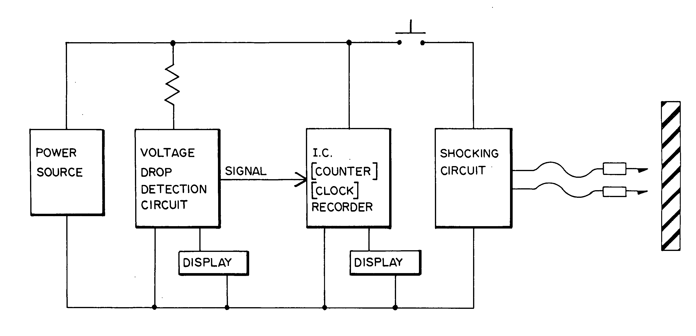
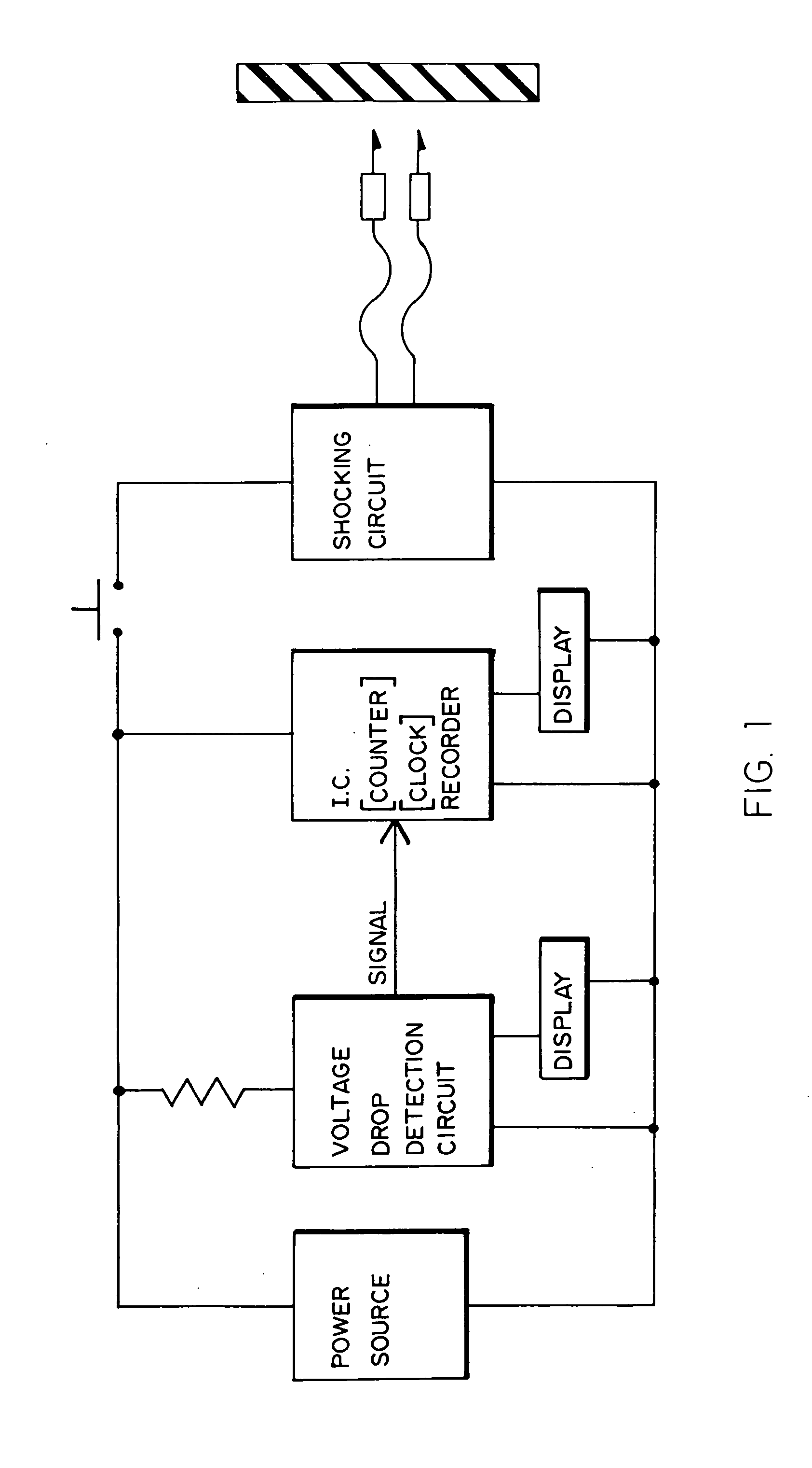
[0018]Referring to the accompanying drawings, and to FIG. 1 in particular, it will be seen that the general concept of the invention is disclosed therein. More specifically, a voltage drop detection circuit and a counter or clock-based I.C. recorder, each connected to a display, are interposed between a power source and a high voltage shocking circuit. In a weapon-based configuration, the shocking circuit is adapted for propelling a pair of wire-tethered electrode darts to a remote target. If both such electrode darts successfully impact and adhere to the remote target, the high voltage (i.e., 50 K VOLTS) generated at the shocking circuit, causes an electric current to flow through the target via the wire-tethered darts to disable the target.

[0019]The inventive concept hereof is based upon such current flow causing a voltage drop across the target between the two darts. Those having knowledge in the art of electric circuits will appreciate that if, for any reason, current does not f...


PUM


Abstract

An electronic shocking device comprising a voltage drop detector which signals an integrated circuit to record the occurrence of a shock when the device voltage drops within a preset tolerance corresponding to a recommended level of shocking current. The voltage drop detector or integrated circuit may also activate a display to signal the device operator that the device is actually shocking a subject.

Description

BACKGROUND OF THE INVENTION[0001]1. Field of the Invention[0002]The invention relates generally to the field of shocking devices containing circuitry intended to record and signal an actual shocking event.[0003]2. Prior Art[0004]Numerous types of devices designed to shock humans and other animals exist. The devices range from medical devices, requiring pre-market notification to or pre-market approval from the United States Food and Drug Administration, to weapons, intended to subdue and capture. Descriptions of some of the many general classes of shocking therapeutic medical devices may be found at 21 CFR Parts 876 (Gastroenterology and Urology Devices), 884 (Obstetrical & Gynecological Devices) and 890 (Physical Medicine Devices). Many United States patents for shocking weapons for subduing and capturing human and other animal targets have issued. These patents include U.S. Pat. No. 3,803,463 to Cover, U.S. Pat. No. 4,688,140 to Hammes and U.S. Pat. No. 5,841,622 to McNulty. Such ...

Claims


Application Information

Patent Timeline
Patent Type & Authority Applications(United States)
IPC IPC(8): A61N1/08F41B15/04
CPCA61N1/38F41B15/04H05C3/00H05C1/00F41H13/0025
Inventor MCNULTY, JR., JAMES F.
Owner SAFARILAND
Why Eureka
Try Eureka