Method and system for correcting print image distortion due to irregular print image space topography

a topography and print image technology, applied in the field of envelope printing, can solve the problems of negative impact on machine and human read rate, increased image distortion, and higher likelihood of encountering machine readability problems, so as to improve both machine barcode readability and human readability of printed images. , the effect of preventing image distortion

Active Publication Date: 2007-01-25
PITNEY BOWES INC
View PDF8 Cites 17 Cited by
  • Summary
  • Abstract
  • Description
  • Claims
  • Application Information

AI Technical Summary

Benefits of technology

[0012] The present invention can improve machine read rates to satisfy United States Postal Service (USPS) requirements, by providing a solution for correcting print image distortion through application of appropriate delays to nozzle firing events. By preventing image distortion on a surface having irregular topography, this invention improves bo

Problems solved by technology

These distorted images can negatively affect machine and human read rates.
As envelope velocities get higher, the ink drop will be more displaced from its intended target position, thus causing greater image distortion.
With increased paper velocity, image distortion increases, resulting in higher likelihood of encountering machine readability problems.
Stepped mail introduces a similar problem.
Again, this produces irregularitie

Method used


Image

  • Method and system for correcting print image distortion due to irregular print image space topography
  • Method and system for correcting print image distortion due to irregular print image space topography
  • Method and system for correcting print image distortion due to irregular print image space topography

Examples


Embodiment Construction

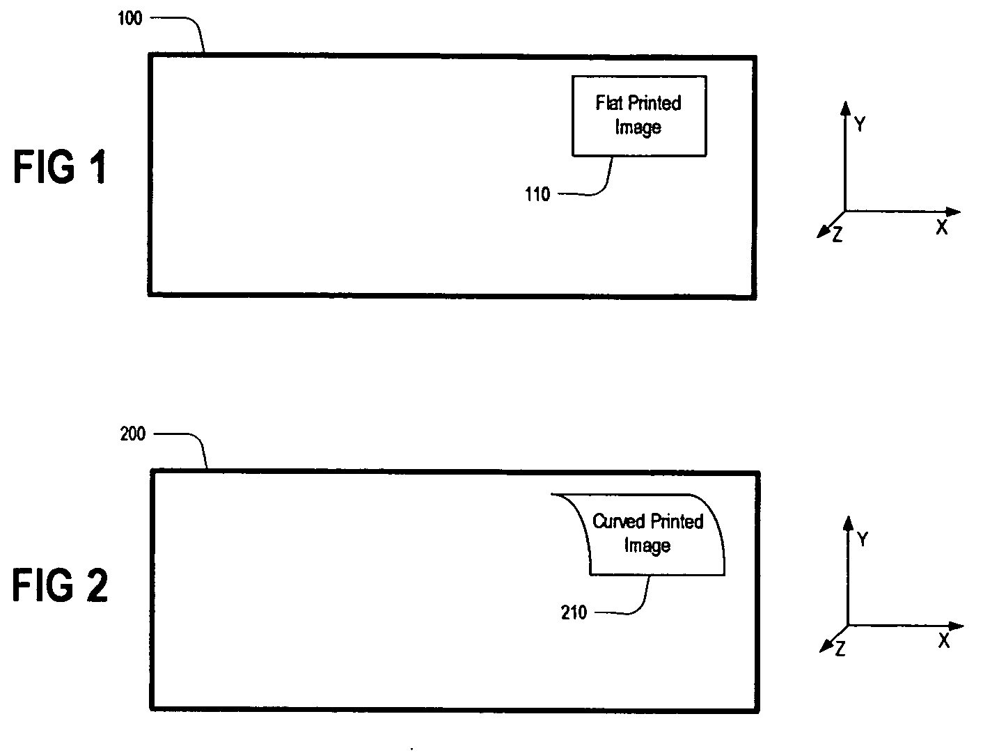
[0021]FIG. 1 shows a flat envelope 100 having a flat printed image 110. This envelope is moving in the x-direction, and will not have any of the difficulties associated with printing on a curved surface. FIG. 2, however, shows a stuffed envelope 200 that consequently will have a curved print image 210. This is the kind of mail piece that the present invention addresses.

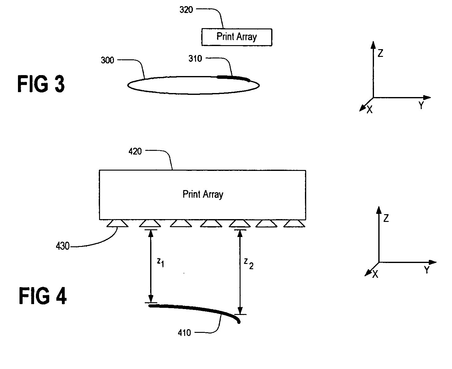
[0022]FIG. 3 shows a mail piece 300 that is moving in the x-direction (i.e. out of the page). The curved printed image 310 will be printed by the print array 320.

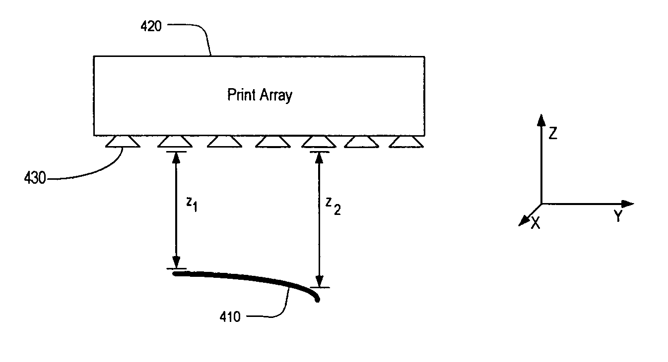
[0023]FIG. 4 shows an enlarged print array 420 for printing the curved printed image 410. According to this embodiment of the present invention, a single line of ink jet nozzles 430 that exist in the print array 420 are positioned perpendicular to the x-direction of paper travel. To correct for print image distortion, a time delay is added to the normal fire event for each nozzle fire, as a function of the relative distance of a point under the nozzle to a ...


PUM


Abstract

A method and system are disclosed for ejecting ink drops from a plurality of ink jet nozzles in order to print on an envelope in a mail piece production process. The envelope has been stuffed and is therefore not flat, especially near the edges. Mail piece composition data is obtained and stored for the mail piece, and based upon that composition data a nozzle delay pattern is determined. For each ink jet nozzle, ink is ejected in accordance with the delay pattern so as to contact a point of the envelope's surface at the same time as drops from other ink jet nozzles.

Description

TECHNICAL FIELD [0001] The present invention relates to printing on envelopes in a mail production process. BACKGROUND OF THE INVENTION [0002] Mail production systems such as those applicable for use with the present invention, are typically used by organizations such as banks, insurance companies and utility companies for producing a large volume of specific mailings where the contents of each mail item are directed to a particular addressee. Also, other organizations, such as direct mailers, use inserts for producing a large volume of generic mailings where the contents of each mail item for each addressee are substantially identical. [0003] A typical inserter system for producing mail will, in some respects, resemble a manufacturing assembly line. Sheets and other raw materials (e.g. enclosures, and envelopes) enter the inserter system as inputs. Then, a plurality of different modules or workstations in the inserter system work cooperatively to process the sheets until a finished...

Claims


Application Information

Patent Timeline
IPC IPC(8): B41J29/38
CPCB41J2/04505B41J2/04556B41J2/04573B41J2/0458G07B2017/00556B41J3/28B41J29/393G07B17/00508G07B2017/00532B41J2/17596
Inventor SUSSMEIER, JOHN W.
Owner PITNEY BOWES INC
Why Eureka
Try Eureka