Wavelength branching filter and optical communication module

a filter and wavelength technology, applied in the field of wavelength branching filter branching light, can solve the problems of increasing the cost, increasing the cost, and the range of 1490 nm to 1650 nm cannot be simultaneously covered, and achieve the effect of low cost and low rectangular property

Inactive Publication Date: 2007-01-25
ALPS ALPINE CO LTD
View PDF2 Cites 139 Cited by
  • Summary
  • Abstract
  • Description
  • Claims
  • Application Information

AI Technical Summary

Benefits of technology

[0011] In the wavelength branching filter according to the embodiment of the present invention, when the first multilayer film disposed in the incoming light side has characteristic in reflecting light of 1490 nm wavelength band and transmitting light of 1310 nm wavelength band, and the second multilayer film disposed in the outgoing light side has characteristic in reflecting light of 1650 nm wavelength band and transmitting light of 1310 nm wavelength band, since light of 1490 nm wavelength band is reflected in the incoming side, the dual focusing of the light can be prevented and light of 1490 nm wavelength band of the second multilayer film has low rectangular property, whereby the thickness of the film can be thinned, thereby the cost-down being achieved.
[0012] Further, in the optical communication module according to the embodiment of the present invention, since the above-referenced wavelength filter is disposed at the intersection position of the optical axes of the light collecting unit and the light emitting unit, the module can be constructed at low cost.

Problems solved by technology

However, the range of 1490 nm to 1650 nm cannot be simultaneously covered in the mixture of SiO2 and Ta2O5 used as a material of a common multilayer film filter.
Though, in this case, positioning is required due to the increase in the number of parts, thereby raising the cost thereof.
However, the wavelength branching filter is fixed within the optical communication module by UV adhesive, whereby the optical communication module can be manufactured at low cost, but since the UN adhesive cannot be used for this material, another fixing method is required, thereby raising the cost thereof.

Method used


Image

  • Wavelength branching filter and optical communication module
  • Wavelength branching filter and optical communication module
  • Wavelength branching filter and optical communication module

Examples


Embodiment Construction

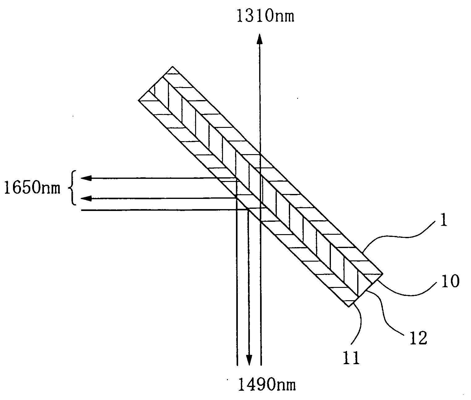
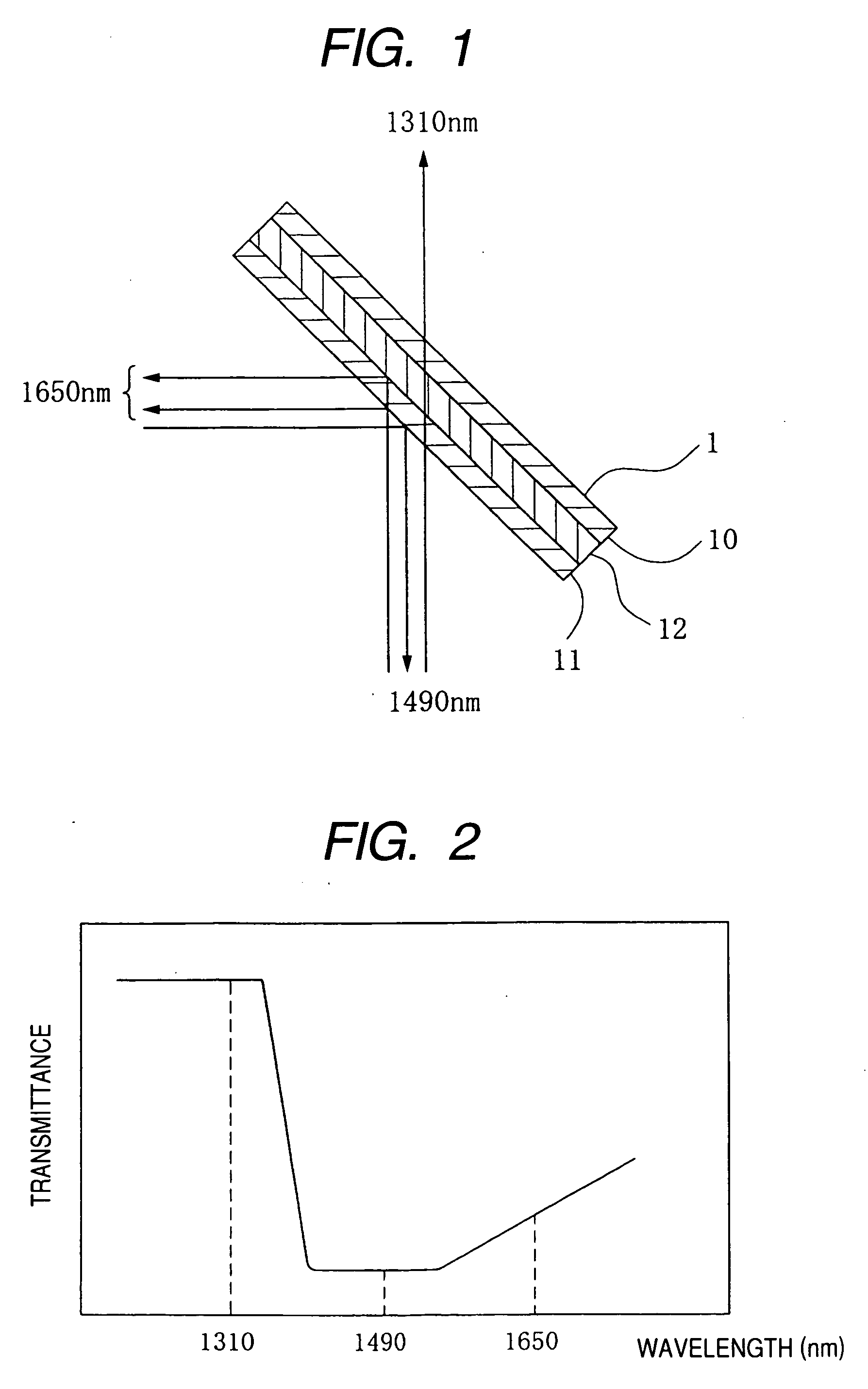
[0018] The embodiments of the present invention will be specifically described with reference to the drawings. FIG. 1 is a cross-sectional view of a wavelength branching filter 1 in this embodiment. As shown in FIG. 1, the wavelength branching filter 1 according to the embodiment of the present invention is constituted by a first multilayer film filter 11 and a second multilayer film filter 12 on a glass substrate 10, all of these first multilayer film filter 11 and second multilayer film filter 12 are achieved from the construction forming the film consisting of SiO2 and Ta2O2 and having the thickness given from the formula below in a multilayer film form and the construction forming the film having the thickness adjusted to constrain the sidelobe in a multilayer film form.

d=λ / 4√n·n0·sin ⊖  (Formula 1)

[0019] Here, d represents the film thickness (nm), λ represents the reflection center wavelength (nm), n represents the refraction index of film, n0 represents the refraction index ...


PUM


Abstract

There is provided a low-cost wavelength branching filter that transmits lights of 1310 nm wavelength band, and reflects light of 1490 nm and 1650 nm wavelength bands. A wavelength branching filter includes a first multilayer film filter 11 positioned in a light incoming side on a glass substrate 10 and a second multilayer film filter 12 positioned in a light outgoing side, and the first multilayer film filter 11 has characteristic in reflecting light of 1490 nm wavelength band and transmitting light of 1310 nm wavelength band, and the second multilayer film filter 12 has characteristic in reflecting light of 1650 nm wavelength band and transmitting light of 1650 nm wavelength band and reflecting light of 1310 nm wavelength band.

Description

BACKGROUND OF THE INVENTION [0001] 1. Field of the Invention [0002] The present invention relates to a wavelength branching filter branching light of a desired wavelength and an optical communication module using the same, particularly, to a wavelength branching filter branching light of a specific wavelength used in the optical communication module and an optical communication module using the same. [0003] 2. Description of the Related Art [0004] In an optical communication module that implements a two-way communication, there has been known a two-wavelength mode in which two-way signal lights have different wavelength. Light of 1310 nm wavelength band and light of 1490 nm wavelength band are generally used as signal light. In addition, light of 1650 nm wavelength band is used as monitor light required for a line construction. The construction in which these lights can be respectively separated is required in the optical communication module. The optical communication module which ...

Claims


Application Information

Patent Timeline
Patent Type & Authority Applications(United States)
IPC IPC(8): F21V9/04G02B5/28G02B6/42
CPCG02B5/285
Inventor KIKUCHI, TOSHIHIRO
Owner ALPS ALPINE CO LTD
Why Eureka
Try Eureka