PRML based magnetic servo position demodulator

a technology of magnetic servo and demodulator, which is applied in the direction of maintaining head carrier alignment, recording signal processing, instruments, etc., can solve the problems of loss of resolution of recorded signal being processed, and it is difficult to detect so as to achieve the precise position of reference marks, the resolution is reduced, and the accuracy is improved.

Inactive Publication Date: 2007-01-25
QUANTUM CORP
View PDF54 Cites 15 Cited by
  • Summary
  • Abstract
  • Description
  • Claims
  • Application Information

AI Technical Summary

Benefits of technology

[0008] In one example, the analog signal is generated by a transducer (e.g., magnetic servo read head, magneto-resistive sensor, etc.). The transducer can be configured to simultaneously read a plurality of channels on the magnetic data storage medium. In one application, the method further comprises utilizing PRML to extract data from the analog signal. The PRML method can comprise sampling the analog signal at predefined intervals utilizing an analog to digital converter, and utilizing a state machine to determine the presence or absence of a recorded signal. The sampling nature of the PRML method can lead to loss in resolution of the recorded signal being processed, and thus, making it harder to detect the precise position of the reference mark. One approach in determining a refined position of the reference mark comprises determining an approximate position of a peak in the analog signal representative of the position of the reference mark, and further determine a more precise position of the reference mark utilizing a mathematical model (e.g., Lagrange interpolation equation, etc.). The mathematical model can be utilized to predict the actual peak position within the analog signal based on the calculation of the digital data stream.

Problems solved by technology

The sampling nature of the PRML method can lead to loss in resolution of the recorded signal being processed, and thus, making it harder to detect the precise position of the reference mark.

Method used


Image

  • PRML based magnetic servo position demodulator
  • PRML based magnetic servo position demodulator
  • PRML based magnetic servo position demodulator

Examples


Embodiment Construction

[0030] The following detailed description should be read with reference to the drawings, in which identical reference numbers refer to like elements throughout the different figures. The drawings, which are not necessarily to scale, depict selective embodiments and are not intended to limit the scope of the invention. The detailed description illustrates by way of example, not by way of limitation, the principles of the invention. This description will clearly enable one skilled in the art to make and use the invention, and describes several embodiments, adaptations, variations, alternatives and uses of the invention, including what is presently believed to be the best mode of carrying out the invention.

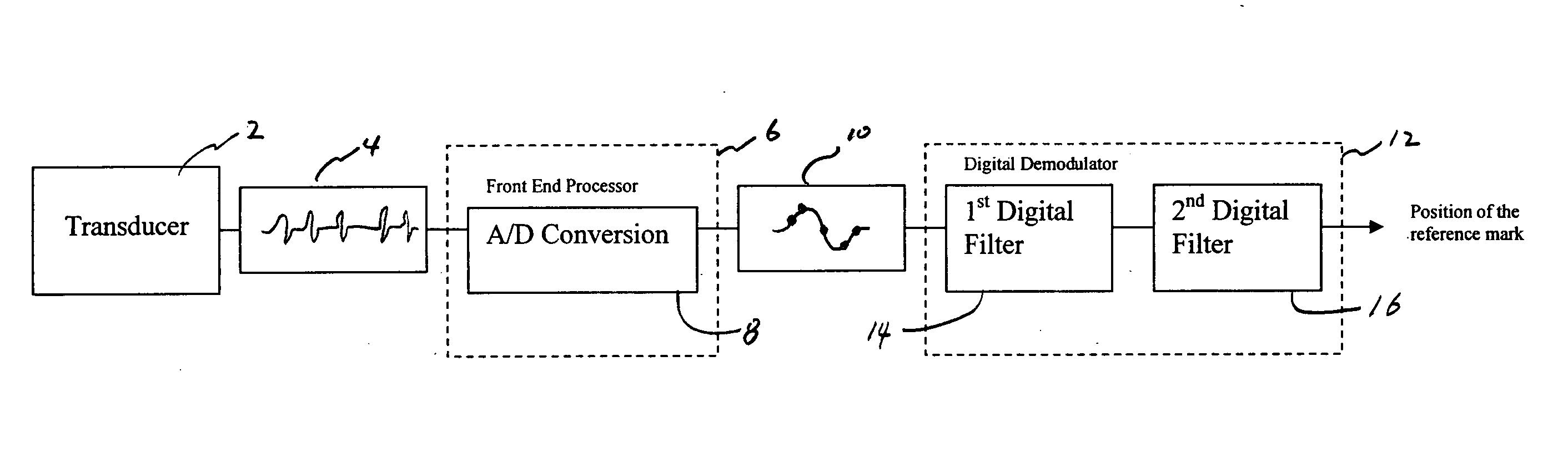
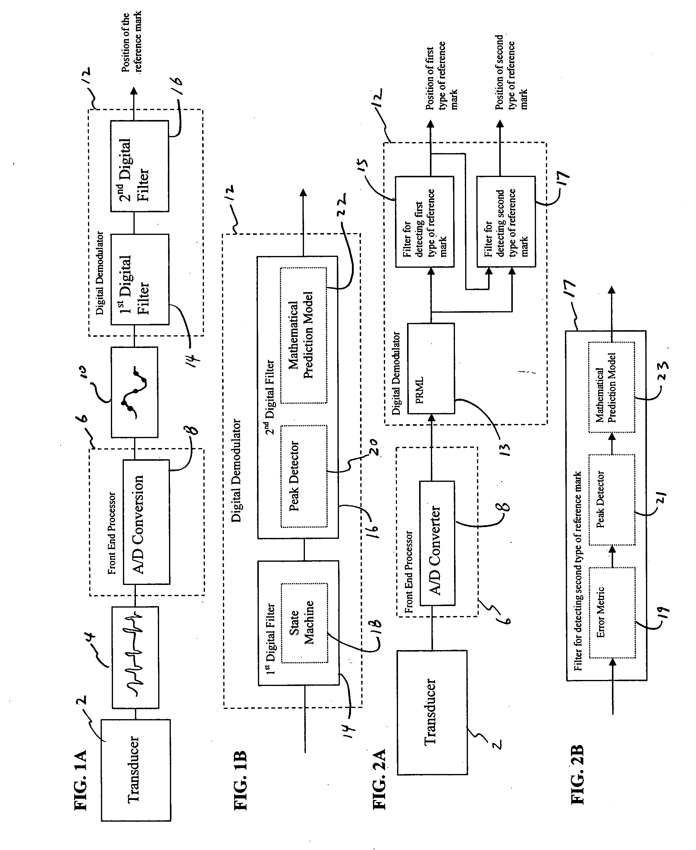
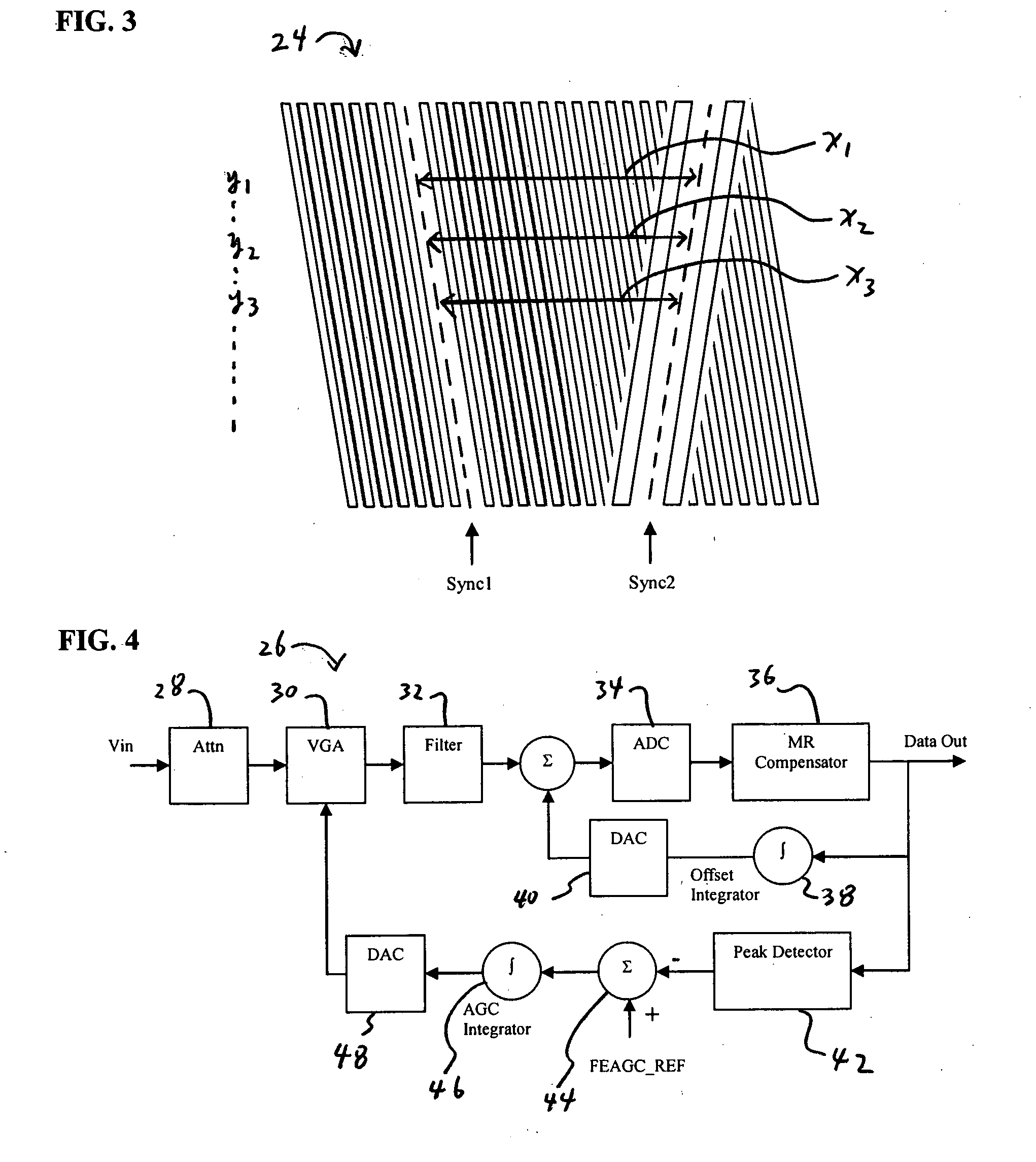
[0031] PRML based magnetic servo position demodulator is used herein as an example application of the reference mark detection apparatus, in order to illustrate the various aspects of the invention disclosed herein. In light of the disclosure herein, one of ordinary skill in the art...


PUM

PropertyMeasurementUnit
lengthaaaaaaaaaa
lengthaaaaaaaaaa
magneticaaaaaaaaaa

Abstract

Apparatuses and methods for detecting reference marks on magnetic data storage mediums are described herein. In one variation, the apparatus comprises a magnetic servo position demodulator operable to extract information from the magnetic data storage medium utilizing Partial Response/Maximum Likelihood (PRML) technique. Synchronization marks stored within the PRML channel is then detected utilizing a digital filter. For each of the detected synchronization mark, a further refined position of the synchronization mark can be determined utilizing a mathematical prediction model.

Description

FIELD OF THE INVNENTION [0001] The invention is related generally to the field of data storage systems. In one aspect of the invention, apparatuses and methods disclosed herein can be implemented for detecting reference marks in magnetic data storage mediums. BACKGROUND [0002] Various data recording and recovery schemes have been developed over the years for storage of information on a magnetic medium. One example utilizes peak detection to demodulate magnetically encoded data from a magnetic storage medium. Another example utilizes Partial Response / Maximum Likelihood (PRML) detectors, which offers an improvement in signal to noise ratio (SNR) in comparison to the peak detection approach. PRML have been widely adapted in various magnetic data storage medium in recent years. However, until recently, PRML read channels have been typically constructed with an analog to digital converter (ADC) inside the timing recovery loop, resulting in a complex integration process, which has slowed ...

Claims


Application Information

Patent Timeline
Patent Type & Authority Applications(United States)
IPC IPC(8): G11B20/08
CPCG11B20/10009G11B20/10055G11B20/10175G11B20/10527G11B2220/90G11B27/324G11B2020/10953G11B2020/1484G11B27/10
Inventor NORTON, DAVID E. JR.
Owner QUANTUM CORP
Why Eureka
Try Eureka