Auto-stereoscopic display device

a display device and display device technology, applied in optics, instruments, electrical devices, etc., can solve the problems of shallow three-dimensional image with little depth perception, undesirable sub-vertical and horizontal resolution, etc., to achieve the effect of sacrificing resolution, increasing the number of views displayed, and “consuming” both vertical and horizontal resolution

Inactive Publication Date: 2017-10-31
KONINK PHILIPS ELECTRONICS NV
View PDF29 Cites 3 Cited by
  • Summary
  • Abstract
  • Description
  • Claims
  • Application Information

AI Technical Summary

Benefits of technology

[0008]It is an object of the invention to provide a display having a good image resolution, a wide viewing angle and a good perception of depth.
[0012]Each view is typically deflected so that it fills the substantially dark angles between the undeflected views. A typical deflection angle is about half a degree. In this way the need for defocusing of the display to reduce the effect of the dark angles may be reduced or eliminated. In many cases the image forming means is composed of pixels giving of display light and dark regions separating the pixels. The dark regions may be formed by a black mask. The view forming means also image these dark regions between the views at angels called the dark angles. The effect of dark angles is also commonly known as dark banding due to dark bands separating the views observed by the viewer. One way to reduce dark banding is to place the image forming means just out of focus from the view forming means, therewith blurring the image observed by the viewer somewhat and smearing the dark bands.
[0013]If the image forming means is sequentially driven with data for first and second pluralities of views in synchronization with the operation of the view deflecting means, then the number of views may effectively be doubled without any resolution loss. If the image forming means is constantly driven with data for the same plurality of views, then the angle of each view may be increased and, as mentioned above, the need for defocusing of the display to reduce the effect of the dark angles may be reduced or eliminated.
[0020]Arrays of birefringent prisms and second prisms, each having a saw tooth arrangement, may be provided so as to minimize the thickness of the respective layers. The prisms may or may not be aligned with the view forming elements.
[0044]U.S. Pat. No. 6,064,424 discloses an auto-stereoscopic display device similar to that described above, except that the elongate lenticular elements are slanted at an angle to the column direction of the display panel. By slanting the lenticular elements, some of the reduction in horizontal resolution, which would otherwise be required, is transferred to the vertical resolution. It thus becomes possible to “consume” both vertical and horizontal resolution to increase the number of views displayed by the device. Nevertheless, it is still necessary to sacrifice resolution to obtain a display having a wide viewing angle and / or a good perception of depth.

Problems solved by technology

This substantial difference between vertical and horizontal resolution is undesirable.
However, such a display provides a shallow three dimensional image with little perception of depth.

Method used


Image

  • Auto-stereoscopic display device
  • Auto-stereoscopic display device
  • Auto-stereoscopic display device

Examples


Embodiment Construction

[0056]The invention provides an auto-stereoscopic display device of the type that has an image forming element and a view forming element. The display may be a multi-view auto-stereoscopic display. The device comprises a driving means in the form of an integrated circuit, incorporated within a chip or computer which is arranged to sequentially drive each pixel with information for different views. The different views are projected in different directions by switching a view deflecting means in synchronization with the driving of the display pixels. The different views are thereby sequentially projected by the view deflecting means in different directions.

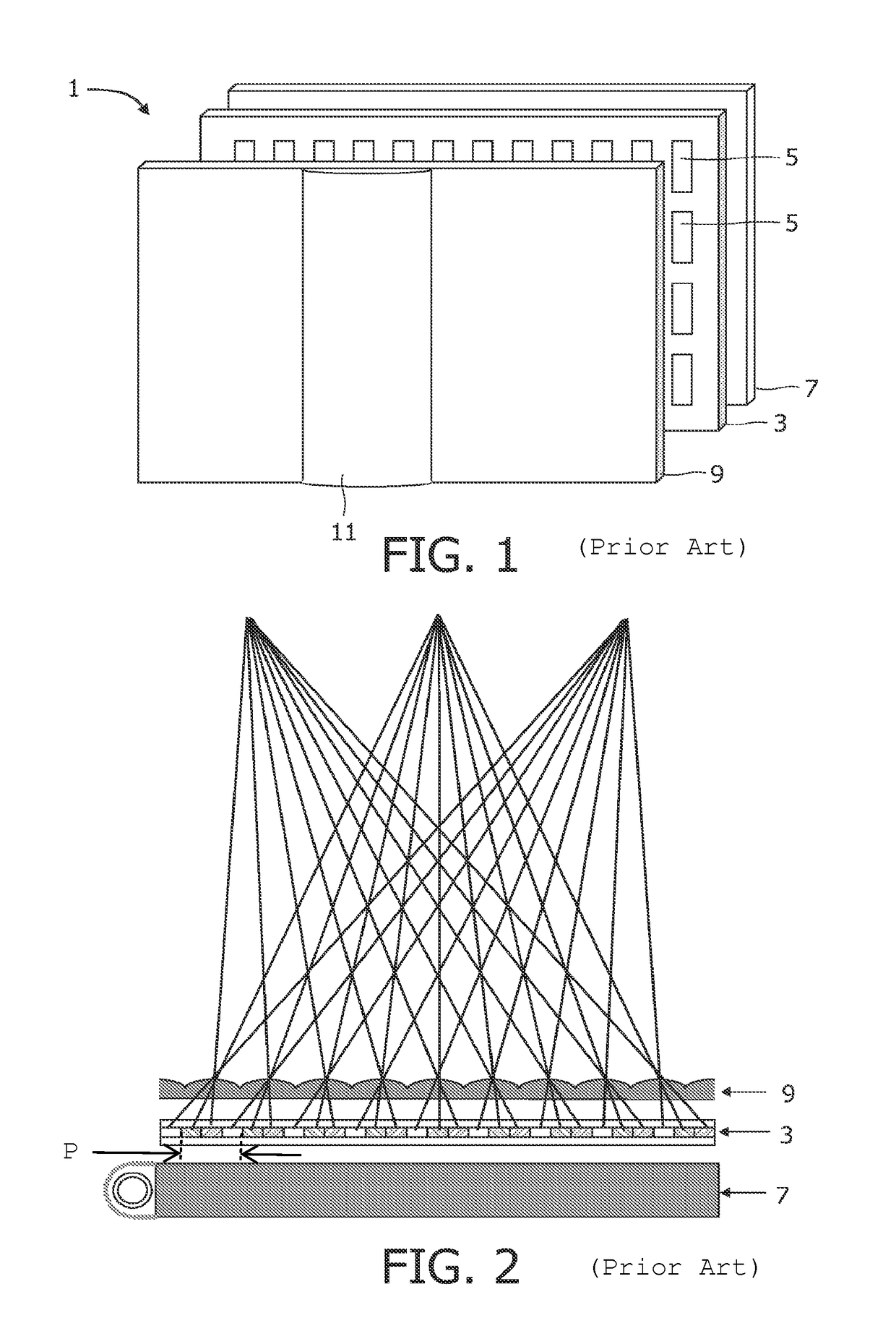
[0057]FIG. 1 is a schematic perspective view of a known multi-view auto-stereoscopic display device 1. The known device 1 comprises a liquid crystal display panel 3 of the active matrix type that acts as an image forming means to produce the display.

[0058]The display panel 3 has an orthogonal array of display pixels 5 arranged in ro...


PUM


Abstract

An auto-stereoscopic display device includes a display panel having an array of display pixels for producing a display; and a view forming unit having an array of view forming elements. Each view forming elements is configurable to focus the outputs of groups of the display pixels into views projected towards a user in different directions. The display device further includes a view deflecting unit to selectably change the directions in which the plurality of views is projected towards the user. The view deflecting unit includes at least one birefringent prism having a first refractive index for light having a first polarization direction and a second refractive index for light having a second polarization direction. The view deflecting unit further includes a polarization switch in registration with the birefringent prism for providing the birefringent prism with display light having the first or second polarization direction.

Description

FIELD OF THE INVENTION[0001]This invention relates to an auto-stereoscopic display device comprising image forming means, such as a display panel having an array of display pixels, and view forming means. The view forming means may be an array of lenticular elements arranged over the image forming element through which the display pixels are viewed. The invention also relates to a method of driving an auto-stereoscopic display device.BACKGROUND OF THE INVENTION[0002]A known auto-stereoscopic display device is described in GB 2196166 A. This known device comprises a two dimensional liquid crystal display panel having a row and column array of display pixels acting as an image forming element to produce the display. An array of elongate lenticular elements extending parallel to one another overlies the display pixel array and acts as a view forming element. The display pixels are observed through these lenticular elements by a user or viewer.[0003]The lenticular elements are provided ...

Claims


Application Information

Patent Timeline
Patent Type & Authority Patents(United States)
IPC IPC(8): G02B27/22H04N13/04G02B27/26G02B30/25
CPCH04N13/0411G02B27/2242H04N13/0447G02B27/26H04N13/0404G02B27/2285G02B30/25G02B30/36G02B30/54H04N13/305H04N13/312H04N13/351G02F1/1335
Inventor HIDDINK, MARTIN GERARD HENDRIKDE ZWART, SIEBE TJERKWILLEMSEN, OSCAR HENDRIKUSVISSENBERG, MICHEL CORNELIS JOSEPHUS MARIEKRAAN, THOMAS CASPAROP DE BEECK, MARC JOSEPH RITAMUIJS, REMCO THEODORUS JOHANNES
Owner KONINK PHILIPS ELECTRONICS NV
Why Eureka
Try Eureka