Image playback apparatus and playback method
a playback apparatus and image technology, applied in the field of playback apparatus and playback method, can solve the problems of user misunderstanding and believing that no signal is recorded
- Summary
- Abstract
- Description
- Claims
- Application Information
AI Technical Summary
Benefits of technology
Problems solved by technology
Method used
Image

Examples
first embodiment
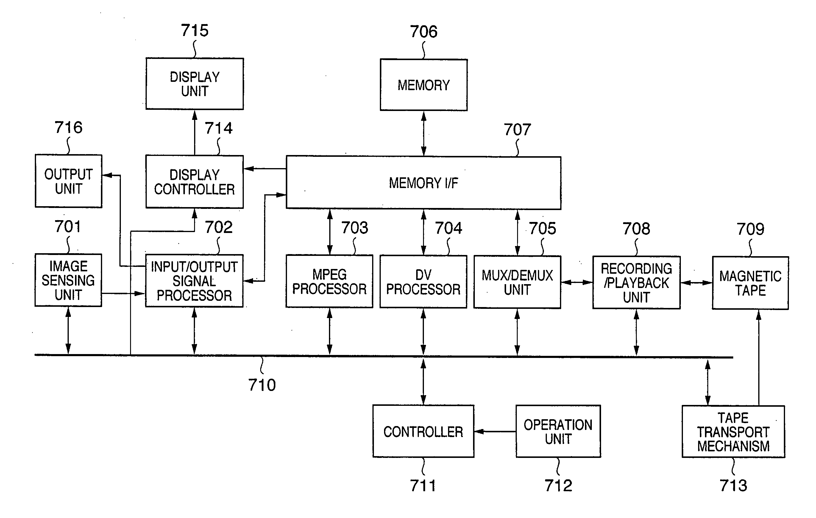
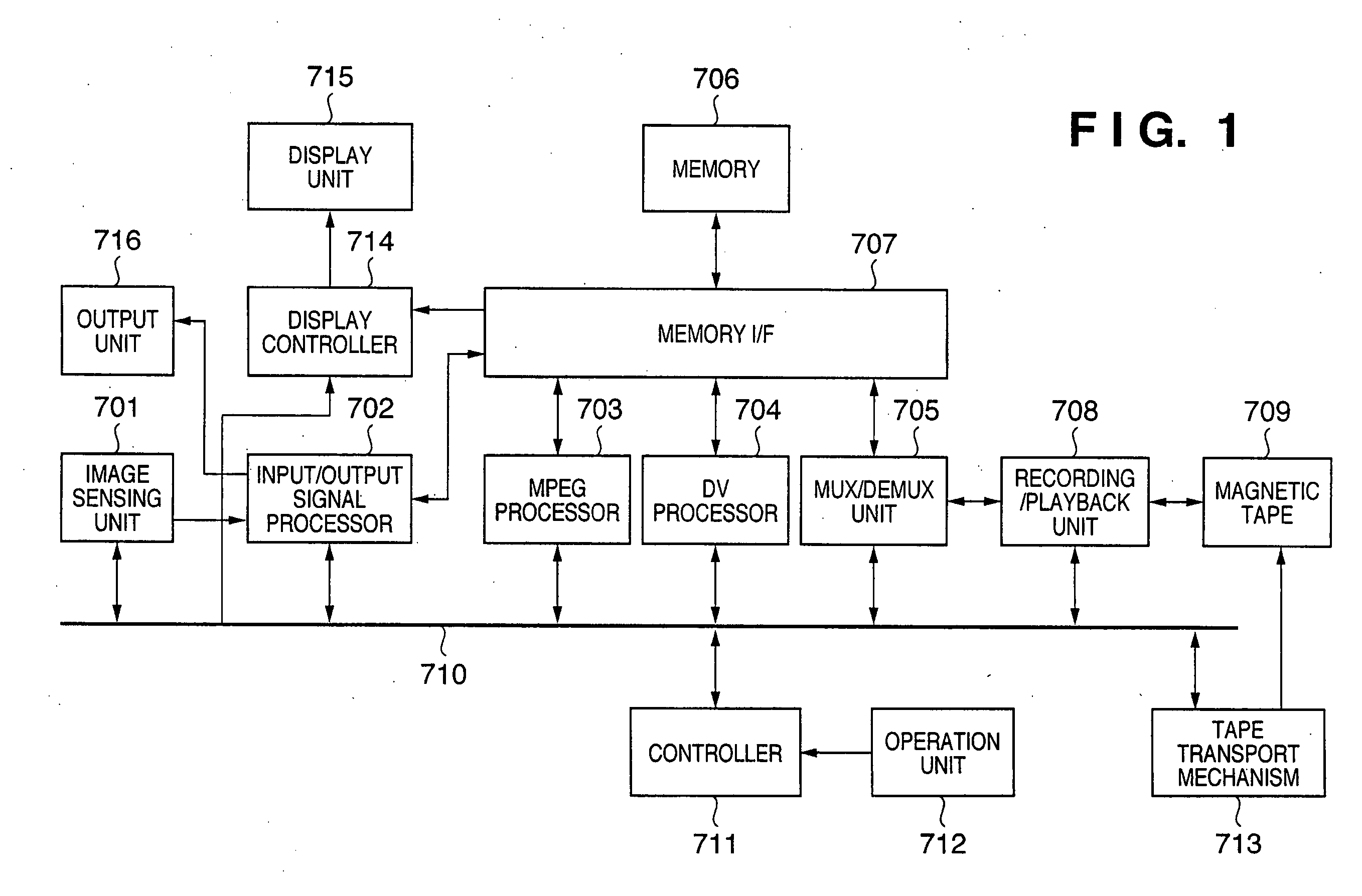
[0025]FIG. 1 is a block diagram showing an example of the arrangement of a digital video camera (DVC) as an embodiment of a playback apparatus according to the present invention.
[0026] The video camera shown in FIG. 1 can record and play back an SD image signal in the DV format and an HD image signal in the HDV format. The user can arbitrarily switch between the DV format and the HDV format upon recording by operating an operation unit 712.
[0027] Referring to FIG. 1, an image sensing unit 701 is used to photograph an object, and outputs an SD or HD image signal. An input / output signal processor 702 applies known signal processing to the image signal output from the image sensing unit 701, and outputs the image signal that has undergone the signal processing to a memory I / F 707. Furthermore, the input / output signal processor 702 converts an image signal read out via the memory I / F 707 to a format suited to output in a playback mode.
[0028] An MPEG processor 703 encodes and decodes ...
second embodiment
[0076] The second embodiment of the present invention will be described below. This embodiment is substantially the same as the aforementioned first embodiment, except for some processes in the method of playing back an image signal upon execution of the REC review function. Therefore, in the following description, the same reference numerals as those in FIGS. 1 to 5 denote the same parts as in the first embodiment, and a detailed description thereof will be omitted.
[0077]FIG. 6 is a conceptual view showing an example of information recorded on the magnetic tape 709 and an image displayed upon execution of the REC review function.
[0078] As shown in FIG. 6, a tape stop position 406 (full inverted-triangle mark in FIG. 6) is located near a boundary 405 between a DV format region 402 and an HDV format region 403. When the REC review function is executed in this state, image signals recorded in different recording formats are played back during single execution of the REC review funct...
third embodiment
[0084] The third embodiment of the present invention will be described below. This embodiment is substantially the same as the aforementioned first and second embodiments, except for an image displayed during switching (transition period) when switching of the internal processing occurs during execution of the REC review function. Therefore, in the following description, the same reference numerals as those in FIGS. 1 to 6 denote the same parts as in the first and second embodiments, and a detailed description thereof will be omitted.
[0085]FIG. 7 is a conceptual view showing an example of an image displayed upon execution of the REC review function.
[0086] As shown in FIG. 7, assume that the tape position moves into the HDV format region while a playback image 407 based on an image signal recorded in the DV format is displayed. As a result, the digital video camera begins to switch the internal processing to a state wherein it can display a playback image 509 based on an image sign...
PUM
 Abstract
Description
Claims
Application Information
 - R&D
- Intellectual Property
- Life Sciences
- Materials
- Tech Scout
- Unparalleled Data Quality
- Higher Quality Content
- 60% Fewer Hallucinations
Browse by: Latest US Patents, China's latest patents, Technical Efficacy Thesaurus, Application Domain, Technology Topic, Popular Technical Reports.
© 2025 PatSnap. All rights reserved.Legal|Privacy policy|Modern Slavery Act Transparency Statement|Sitemap|About US| Contact US: help@patsnap.com