Engine controller and control method

a technology of engine controller and control method, which is applied in the direction of mechanical equipment, propulsion parts, transportation and packaging, etc., can solve the problems of idling speed waste, engine speed not being quickly increased, and poor controllability

Active Publication Date: 2007-01-25
DENSO CORP
View PDF4 Cites 28 Cited by
  • Summary
  • Abstract
  • Description
  • Claims
  • Application Information

AI Technical Summary

Benefits of technology

[0010] According to one aspect of the present invention, an engine speed controller is provided to a vehicle energy control system that includes an engine controller, a generator controller, and an auxiliary device controller. The engine controller controls an engine, which drives a generator, an auxiliary device, and a vehicle. The generator generates electricity and supplying the electricity to a battery and a plurality of current consumers. The generator controller controls the generator. The auxiliary device controller controls the auxiliary device. The engine speed controller performs a feedback control such that engine speed substantially coincides at a target value. The engine speed controller includes an electric power generation calculation unit that calculates one of a requested power generation and a present power generation of the generator. The engine speed controller further includes an engine speed changing unit that evaluates tendency of power generation on the basis of the one of the requested power generation and the present power generation. The engine speed changing unit requests increase in the engine speed when the engine speed changing unit determines the power generation to be inclined toward shortage. The engine speed changing unit requests decrease in the engine speed when the engine speed changing unit determines the power generation to be inclined toward excess.
[0011] Alternatively, the engine speed controller includes an engine torque calculation unit that calculates one of a requested engine torque and a present engine torque of the engine. The engine speed controller further includes an engine speed changing unit that evaluates tendency of engine torque on the basis of the one of the requested engine torque and the present engine torque. The engine speed changing unit requests increase in the engine speed when the engine speed changing unit determines the engine torque to be inclined toward shortage. The engine speed changing unit requests decrease in the engine speed when the engine speed changing unit determines the engine torque to be inclined toward excess.
[0012] Alternatively, a control method includes calculating one of a requested power generation and a present power generation performed using a generator driven by an engine for generating electricity. The method further includes evaluating tendency of power generation on the basis of the one of the requested power generation and the present power generation. The method further includes requesting increase in the engine speed when determining the power generation to be inclined toward shortage. The method further includes requesting decrease in the engine speed when determining the power generation to be inclined toward excess. The method further includes operating the engine speed in accordance with the request of the engine speed.
[0013] Alternatively, a control method includes calculating one of a requested engine torque and a present engine torque of an engine that drives a generator for generating electricity. The method further includes evaluating tendency of engine torque on the basis of the one of the requested engine torque and the present engine torque. The method further includes requesting increase in the engine speed when determining the engine torque to be inclined toward shortage. The method further includes requesting decrease in the engine speed when determining the engine torque to be inclined toward excess. The method further includes operating the engine speed in accordance with the request of the engine speed.

Problems solved by technology

Consequently, controllability is not necessarily excellent.
In the first control, adverse effects due to the opposite acts are not taken into consideration, consequently the idling speed may be wastefully operated.
In addition, the engine speed may not be quickly increased from the idling rotation.
Accordingly, shortage in engine speed may be continued, and such continuous shortage exerts an adverse influence to the battery life.
However, in this case, control response may become excessively quick, consequently the control may cause hunting.
In these simple structures, effect produced by the controls may be limitative.

Method used


Image

  • Engine controller and control method
  • Engine controller and control method
  • Engine controller and control method

Examples


embodiment

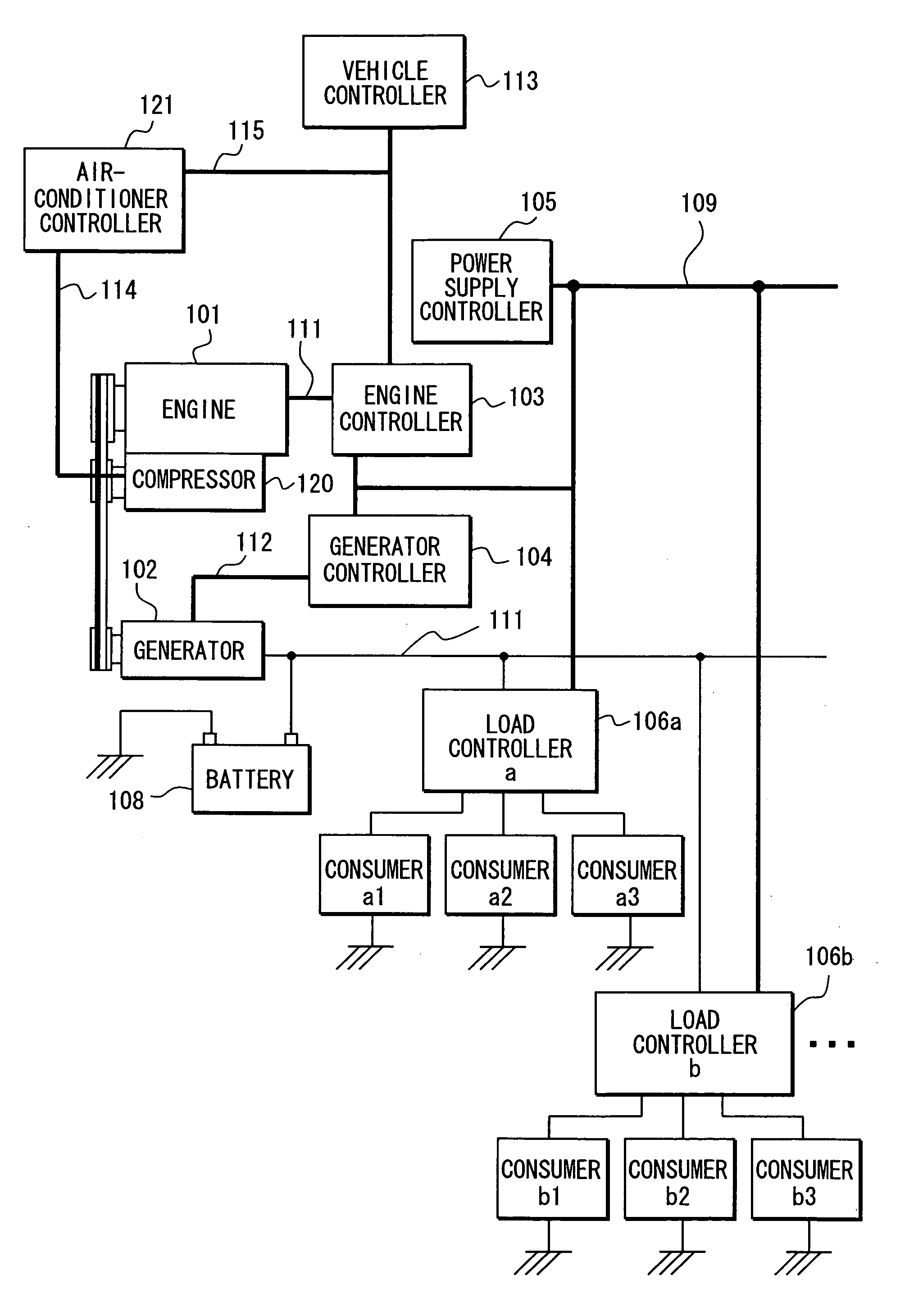
[0026] A vehicle energy control system will be described with reference to FIG. 1.

[0027] An engine 101 is connected to an electric generator 102 and a compressor 120 via a belt. The compressor 120 is provided for airconditioning of a vehicle. The electric generator 102 is connected to a battery 108, load controllers 106a, 106b, and another load controller (not shown) via a power supply line 111 to construct a power supply system.

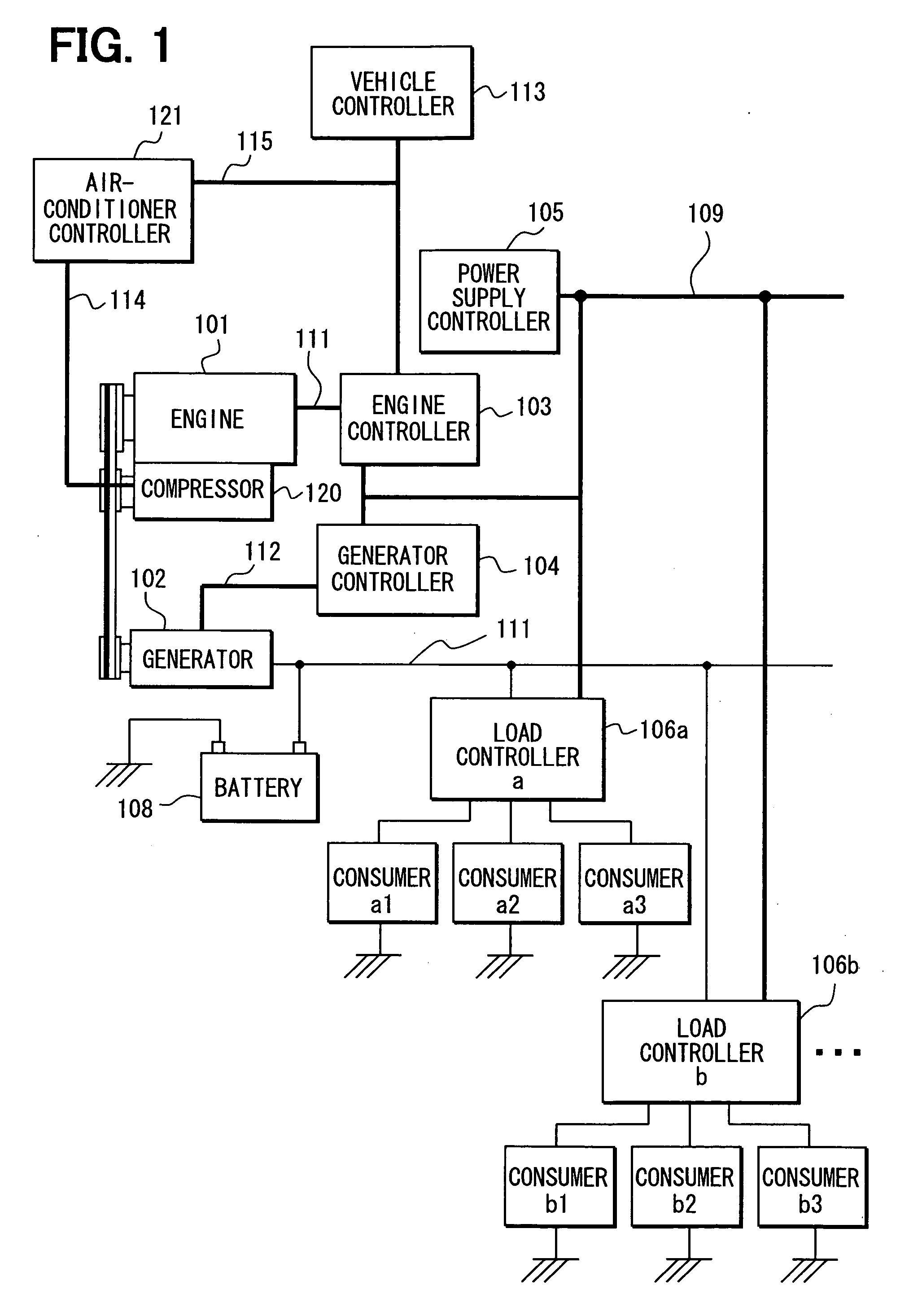
[0028] An engine controller 103 controls the engine 101, an electric generator controller 104, a power supply controller 105, an air-conditioner controller (auxiliary device controller) 121, and a vehicle controller 113. The electric generator controller 104 controls the electric generator 102. The power supply controller 105 controls the power supply system. The air-conditioner controller 121 controls an air-conditioner including the compressor 120. The vehicle controller 113 controls various operations such as a cruising operation of the vehicle.

[0029] ...

modified example

[0076] A description of a power generation control according to a modified example of the above embodiments will be given in reference to FIGS. 13, 14. In this modified example, the engine speed is changed in response to a request for changing engine speed in the power generation control. This request is caused by the power generation control shown in FIG. 7 or FIG. 8.

[0077] As referred to FIG. 13, in step S300, the power supply controller 105 evaluates whether change of the engine speed has been actually completed in the engine speed control described above. In step S302, when the change has been actually completed, the power supply controller 105 changes authorized torque and transmits the authorized torque to the electric generator controller 104. The power supply controller 105 authorizes using the authorized torque, which is power generating torque in according with the maximum generation Pmax corresponding to a new engine speed. The authorized torque is the engine torque comp...

modified embodiment

[0079] In this modified embodiment, the requested electric power P is power consumption of the respective current consumers the including current consumers a1 to a3, b1 to b3. Alternatively, the requested electric power P is the charged and discharged electric power of the battery 108 added to the power consumption of the respective current consumers including the current consumers a1 to a3, b1 to b3.

[0080] As shown in FIG. 15, a power generating apparatus 130 is connected to the power supply system, in addition to the electric generator 102. In this structure, the requested electric power generation for the electric generator 102 may not be calculated correctly. Therefore, a thermal or optical car-mount power generating apparatus may be applied to the power supply system, as a power generating apparatus.

[0081] In this modified embodiment, the requested electric power P is defined as an amount, which is calculated by subtracting a generated power of the power generating apparatus ...


PUM


Abstract

An engine controller controls an engine, which drives a generator, an auxiliary device, and a vehicle. The generator generates electricity, and supplying the electricity to a battery and a plurality of current consumers. A generator controller controls the generator. An auxiliary device controller controls the auxiliary device. An electric power generation calculation unit calculates one of a requested power generation of the generator and a present power generation of the generator. An engine speed changing unit evaluates tendency of power generation on the basis of the one of the requested power generation and the present power generation. The engine speed changing unit requests increase or decreases in the engine speed when the engine speed changing unit determines the power generation to be inclined toward shortage or excess.

Description

CROSS REFERENCE TO RELATED APPLICATIONS [0001] This application is based on and incorporates herein by reference Japanese Patent Application No. 2005-208605 filed on Jul. 19, 2005. FIELD OF THE INVENTION [0002] The present invention relates to an engine controller and a control method. BACKGROUND OF THE INVENTION [0003] An engine of a vehicle generates torque for generating cruising power, and for driving a generator and an auxiliary device such as a compressor for an air conditioner. [0004] In an example of a first control, an engine in an idling operation generally performs feedback control to maintain the idling speed at a constant speed. In this idling operation of the first control, a target rotation speed in the idling operation is set in accordance with an ON / OFF signal of a compressor. [0005] According to an example of a second control published in each of JP-A-2003-269216 and JP-A-2004-68664, a controller increases the idling speed of an engine to boost electric power gener...

Claims


Application Information

Patent Timeline
Patent Type & Authority Applications(United States)
IPC IPC(8): B60W10/04
CPCB60K6/46B60W10/06B60W10/08B60W10/26B60W10/30Y10T477/675B60W2710/0644B60W2710/0666Y02T10/6217Y02T10/6286Y10T477/679B60W20/102B60W20/11Y02T10/62
Inventor OBAYASHI, KAZUYOSHITANI, KEISUKEYAMASHITA, YUKIHIROKURODA, DAISUKE
Owner DENSO CORP
Why Eureka
Try Eureka