
Wedge Operated Retainer Device And Methods

Inactive Publication Date: 2007-01-25
ANPA MEDICAL
View PDF77 Cites 128 Cited by
  • Summary
  • Abstract
  • Description
  • Claims
  • Application Information

AI Technical Summary

Benefits of technology

[0009] The present invention provides a retainer that is quickly deployed and easy to use and that can be adjusted after placement by a user. The present invention is also directed to suture retainers. The suture retainer of this invention is suitable for percutaneous delivery, particularly where the suture retainer has a tubular profile. Other shapes can be used for other applications without departing from the scope of the invention. This invention also provides a suture retainer that can be adjusted after placement and that enables the user to handle and work with the suture quickly and easily. The suture retainer can have two opposing elements that are positioned such that the elements are juxtaposed with respect to each other. In operation the two elements are engaged by, for example, a coiled body. Additionally, a housing can be provided. The suture retainer enables termination of the suture quickly and effectively.
[0018] Another aspect of the invention provides a method of retaining a surgical suture including the following steps: placing a suture between first and second substantially parallel suture contact surfaces of a suture retainer, the first and second contact surfaces defining a distance between them, one of the first and second contact surfaces defining a suture contact axis; and moving at least one of the first and second contact surfaces along a movement axis not perpendicular to the suture contact axis to reduce the distance between the first and second suture contact surfaces to engage the suture in the retainer. In some embodiments, the method includes the step of increasing the distance between the first and second contact surfaces prior to the placing step. In embodiments in which the suture retainer has a biasing member adapted to bias the first and second contact surfaces toward each other, the increasing step includes the step of applying an opening force to move at least one of the first and second contact surfaces against the biasing member bias. The second moving step of the method may also include the step of removing the opening force.

Problems solved by technology

While forming knots in suture during open surgery is a simple matter, forming knots in sutures during endoscopic surgery can be very difficult.
Current solutions known in the art present a variety of problems for the user, including, limitations with respect to suture size, limitation in materials, inability to adjust suture tightness after placement, difficulty in removing the device, and, typically, the suture device is threaded on the suture before using.

Method used


Image

  • Wedge Operated Retainer Device And Methods
  • Wedge Operated Retainer Device And Methods
  • Wedge Operated Retainer Device And Methods

Examples


Embodiment Construction

[0053] While preferred embodiments of the present invention have been shown and described herein, it will be obvious to those skilled in the art that such embodiments are provided by way of example only. Numerous variations, changes, and substitutions will now occur to those skilled in the art without departing from the invention. As will be appreciated by those of skill in the art, various alternatives to the embodiments of the invention described herein may be employed in practicing the invention. It is intended that the following claims define the scope of the invention and that methods and structures within the scope of these claims and their equivalents be covered thereby.

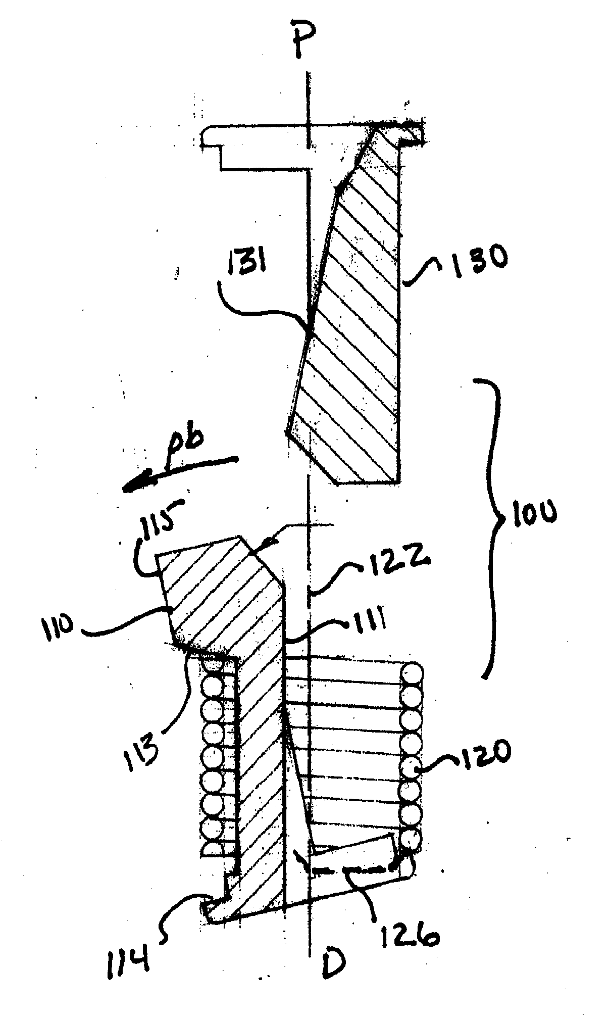
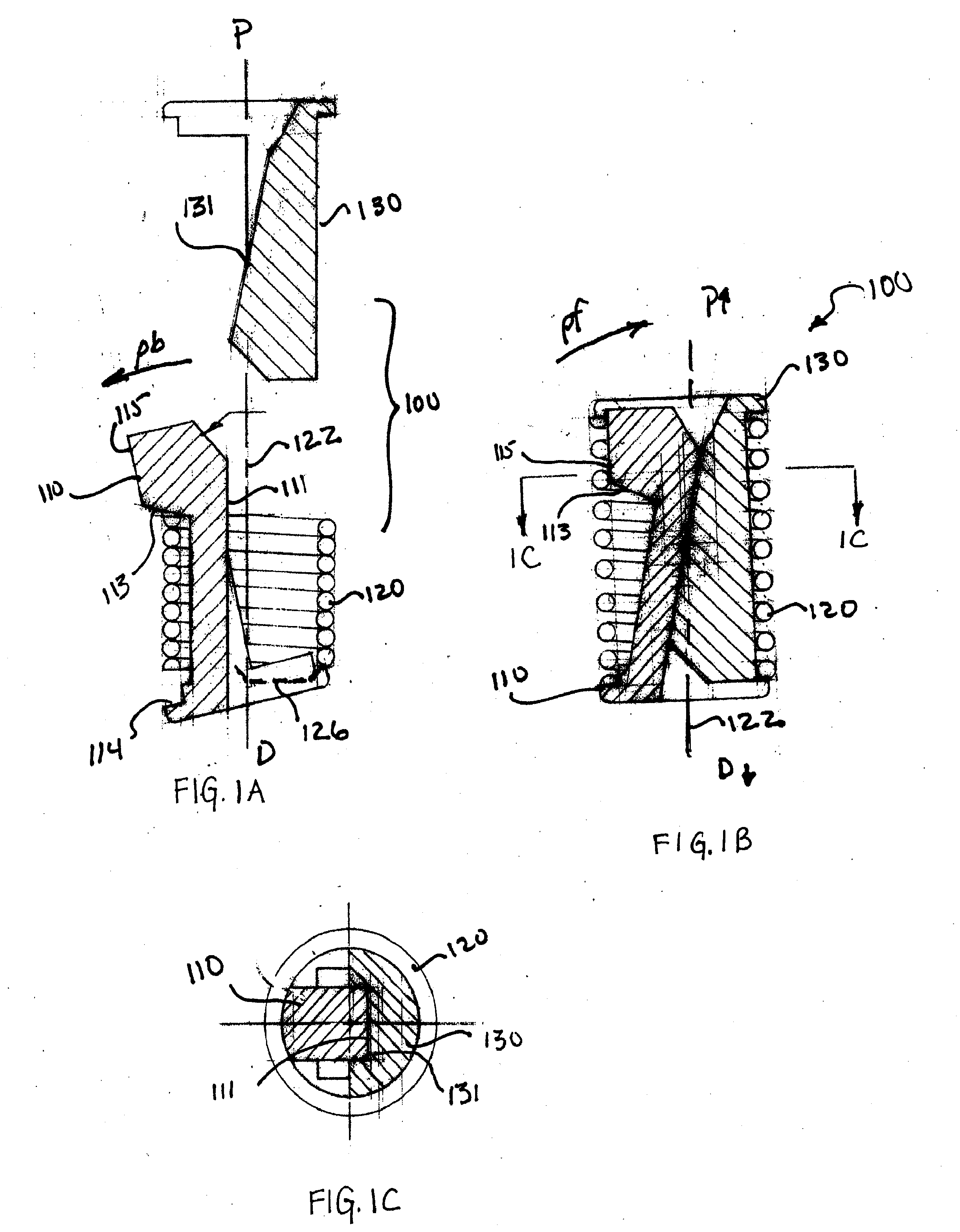
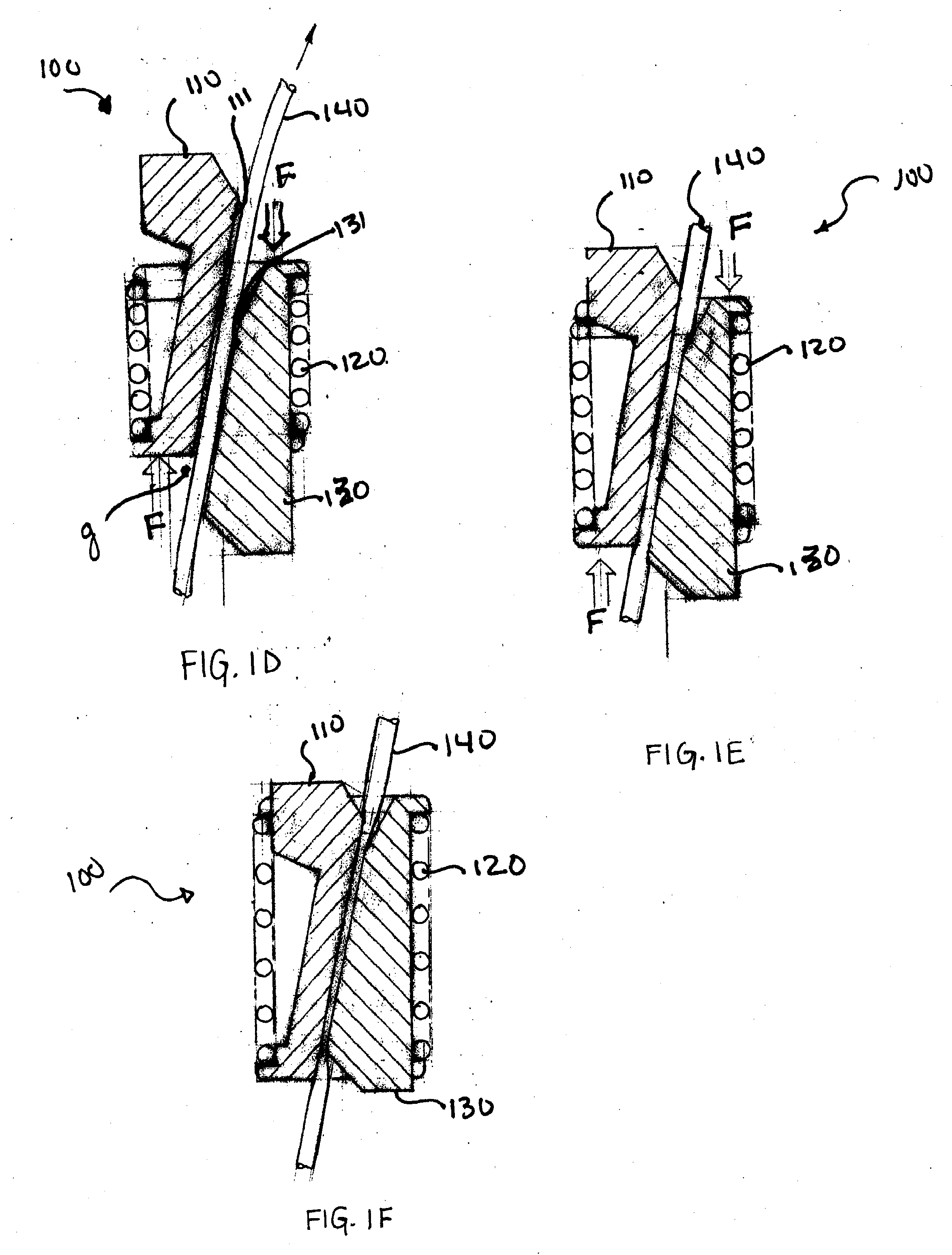
[0054] The present invention is directed to a suture retainer 100 having a proximal end P and a distal end D. The basic components comprising the suture retainer are shown in FIGS. 1A-G. FIG. 1A illustrates the suture retainer 100 having a notched body 110 removably located within a coiled body 120 (e.g., a s...


PUM


Abstract

This invention relates generally to retainers and methods of using retainers. In particular, the invention relates to a suture retainer adapted for application on a subject by use of an introducing device, such as a catheter. The suture retainer comprises two elements, such as wedge-shaped or substantially wedge-shaped elements, that are positioned such that the elements are juxtaposed with respect to each other. In operation the two elements are engaged by a spring which forces the two elements into contact. Additionally, a housing can be provided.

Description

[0001] This application claims the benefit of U.S. Provisional Application No.60 / 701,629, filed Jul. 22, 2005, which is incorporated herein by reference in its entirety.BACKGROUND OF THE INVENTION [0002] (a) Field of the Invention [0003] This invention relates generally to retainers for cordage, line, twine and the like, and methods of using retainers. In particular, the invention relates to a suture retainer adapted for application on a subject by use of an introducing device, such as a catheter. [0004] (b) Description of the Related Art [0005] Sutures are used for a variety of surgical purposes, such as approximation of tissue and ligation of tissue. Most generally, when placing sutures, the strand of suture material to be used has a needle affixed to one end. The needle is passed through the tissue to be approximated or ligated, forming a stitch. The stitch is then tensioned appropriately, and the two ends of the suture, the needle end and the non-needle end, are knotted to retai...

Claims


Application Information

Patent Timeline
IPC IPC(8): A61B17/06
CPCA61B17/0487A61B17/06061A61B2017/0451Y10T24/3996A61B2017/0496Y10T24/3969A61B2017/0488
Inventor JERVIS, JAMES E.ASHLEY, JOHN
Owner ANPA MEDICAL
Learn More