
Switching device for remotely controlling connections of a computer and peripherals over networks

a technology of remote control and peripherals, which is applied in the direction of testing/monitoring control systems, high-level techniques, instruments, etc., can solve the problems of time-consuming and costly repair or maintenance by engineers, and the suspension of services, so as to reduce the number of computer malfunctions to be manipulated

Inactive Publication Date: 2007-01-25
FUJITSU COMPONENENT LTD
View PDF8 Cites 39 Cited by
  • Summary
  • Abstract
  • Description
  • Claims
  • Application Information

AI Technical Summary

Benefits of technology

The present invention provides a switching device that can remotely control a computer on a local side using networks. The switching device includes a remote manipulation notification unit that can notify the local side of the computer of the manipulation of the computer performed at the remote-control side. This prevents incorrect manipulation of the computer and minimizes malfunctions. The remote manipulation notification unit can use a display screen or a sounding body to notify the local side of the computer of the manipulation. The invention also provides a control method and a control program for the switching device.

Problems solved by technology

If the computers fail, provision of services could be suspended to seriously affect the world.
For example, if a server fails or when the maintenance of computers is required, engineers must repair or maintain the computers.
However, a mechanism for remotely maintaining a computer, such as a server or a personal computer, is demanded because the repair or maintenance by an engineer is time-consuming and costly.

Method used


Image

  • Switching device for remotely controlling connections of a computer and peripherals over networks
  • Switching device for remotely controlling connections of a computer and peripherals over networks
  • Switching device for remotely controlling connections of a computer and peripherals over networks

Examples


first embodiment

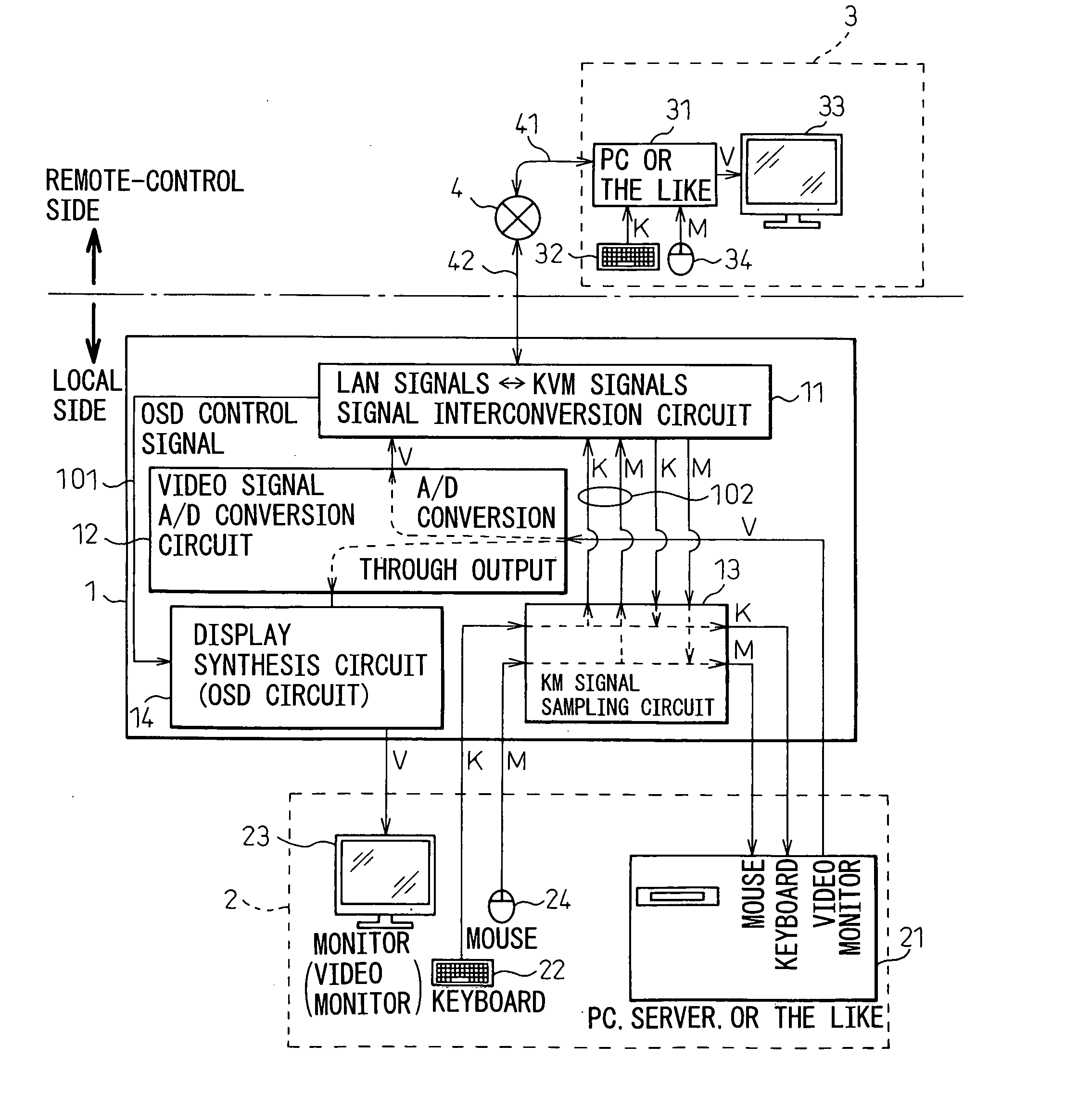
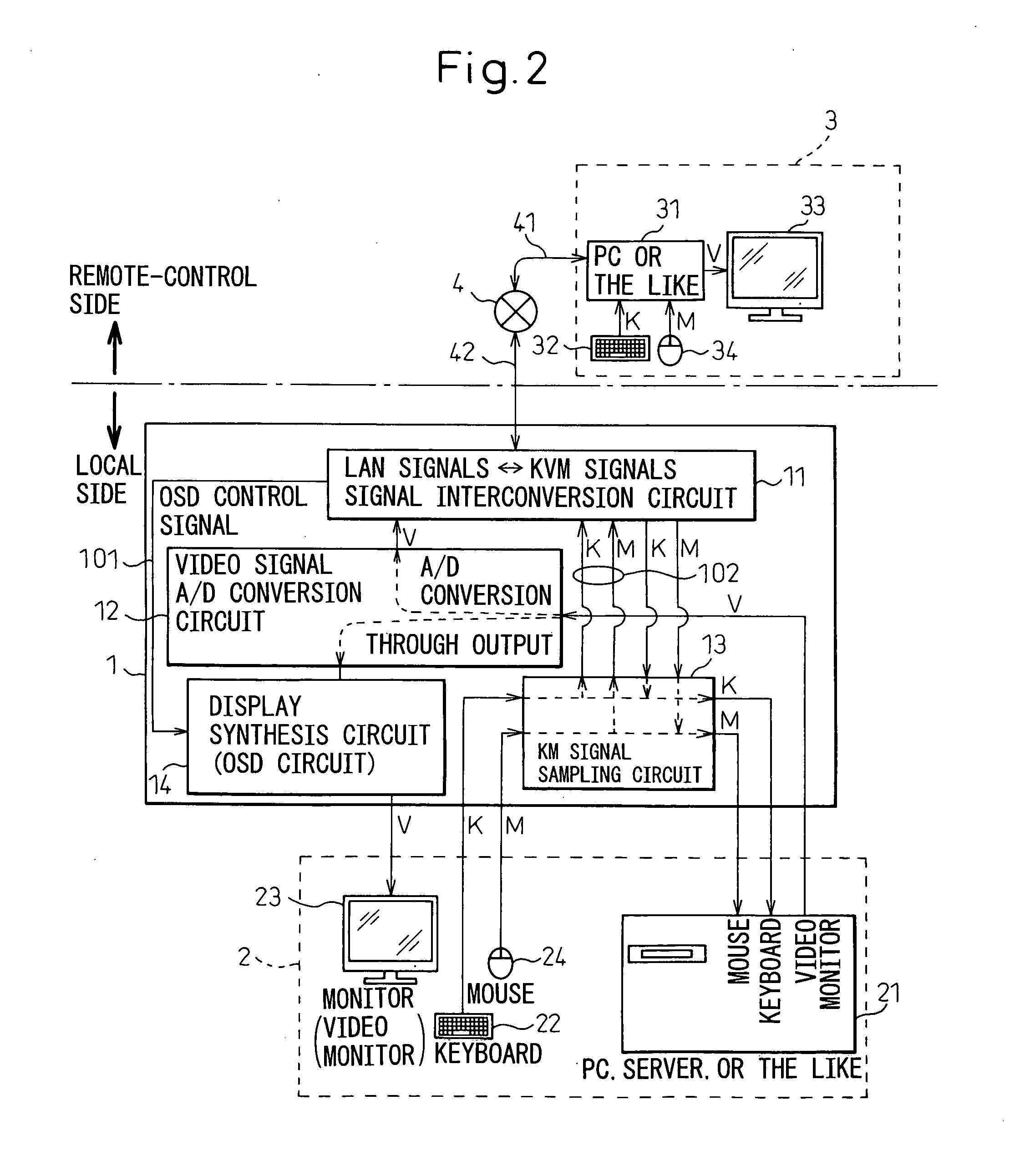
[0052]FIG. 2 is a block diagram schematically showing a switching device in accordance with the present invention. Referring to FIG. 2, there are shown a switching device (IP-KVM switch) 1, a computer 2 to be manipulated (local computer) such as a server or a personal computer (PC) that is an object of manipulation, and equipment 3 to be manipulated in a remote place (remote-control computer).

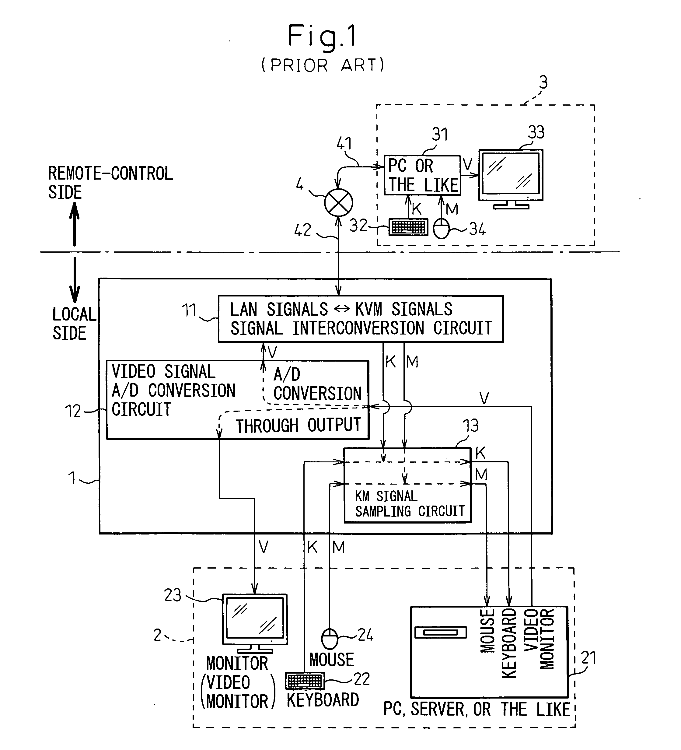
[0053] As apparent from the comparison of FIG. 2 with FIG. 1, the first embodiment includes, in addition to the same components as those of the conventional IP-KVM switch shown in FIG. 1, a display synthesis circuit (on-screen display (OSD) circuit) 14. The configuration of the remote-control computer 3 on the remote-control side and the configuration of the local computer 2 on the local side are substantially identical to the ones described with reference to FIG. 1.

[0054] Specifically, the remote-control computer 3 includes a computer body 31, a keyboard (K) 32, a video monitor (V) 33, and a ...

second embodiment

[0061]FIG. 3 is a block diagram schematically showing a switching device in accordance with the present invention.

[0062] As shown in FIG. 3, according to the second embodiment, message notification software (and driver software) 211 is installed in the local computer 2 (computer body 21) in advance. When the local computer 2 is remotely manipulated at the remote-control computer 3, a message display command sent while being mixed with a K or an M signal is detected, and a message 212 signifying that the local computer 2 is being remotely manipulated, for example, is displayed in a dialog box.

[0063] The message display command is mixed with a keyboard (K) signal or a mouse (M) signal by, for example, an MPU included in the interconversion circuit 11, and is supplied to the local computer 2 via the KM signal sampling circuit 13. Incidentally, a period of time during which the message is displayed may be a certain period of time or an arbitrary period of time. Even in the IP-KVM switc...

third embodiment

[0064]FIG. 4 is a block diagram schematically showing a switching device in accordance with the present invention.

[0065] As shown in FIG. 4, the third embodiment is different from the second embodiment in a point that what is notified by the message notification software 211 is not the message 212 such as a dialog box but is, for example, a buzzer sound, music, or voice 214 output from a loudspeaker 213 included in the computer body 21.


PUM


Abstract

A switching device making it possible to manipulate a computer, which is installed on a local side, at a remote-control side over networks has a remote manipulation notification unit. When the computer is manipulated at the remote-control side, the remote manipulation notification unit notifies the local side, on which the computer is installed, of the manipulation of the computer performed at the remote-control side.

Description

CROSS REFERENCE TO RELATED APPLICATION [0001] This application is based upon and claims the benefit of priority from the prior Japanese Patent Application No. 2005-212472, filed on Jul. 22, 2005, the entire contents of which are incorporated herein by reference. BACKGROUND OF THE INVENTION [0002] 1. Field of the Invention [0003] The present invention relates to a switching device, and a control method and a control program for the switching device. More particularly, the present invention is concerned with a switching device (KVM remote-control device) that remotely controls connections of a computer and peripherals (mainly a keyboard (K), a video monitor (V), and a mouse (M)) over networks. [0004] 2. Description of the Related Art [0005] In the past, a KVM switch has been utilized as a switching device making it possible to manipulate a plurality of computers using one set of a keyboard (K), a video monitor (V), and a mouse (M). Furthermore, an IP-KVM switch remotely controllable t...

Claims


Application Information

Patent Timeline
Patent Type & Authority Applications(United States)
IPC IPC(8): G06F15/16G06F3/0487G06F3/0489
CPCH04L12/12H04L41/0803H04L69/40Y02B60/34H04L67/125H04L41/085Y02D30/50
Inventor KOBAYASHI, MITSURU
Owner FUJITSU COMPONENENT LTD
Learn More