Clock generating circuit having parasitic oscillation suppressing unit and method of suppressing parasitic oscillation using the same

a clock generating circuit and parasitic oscillation technology, applied in oscillating generators, electrical devices, etc., can solve the problems of large current consumption, unpreventable parasitic components, and clock malfunctions, and achieve the effect of eliminating undesired parasitic oscillation and minimizing malfunctions

Inactive Publication Date: 2014-10-09
SAMSUNG ELECTRO MECHANICS CO LTD
View PDF2 Cites 2 Cited by
  • Summary
  • Abstract
  • Description
  • Claims
  • Application Information

AI Technical Summary

Benefits of technology

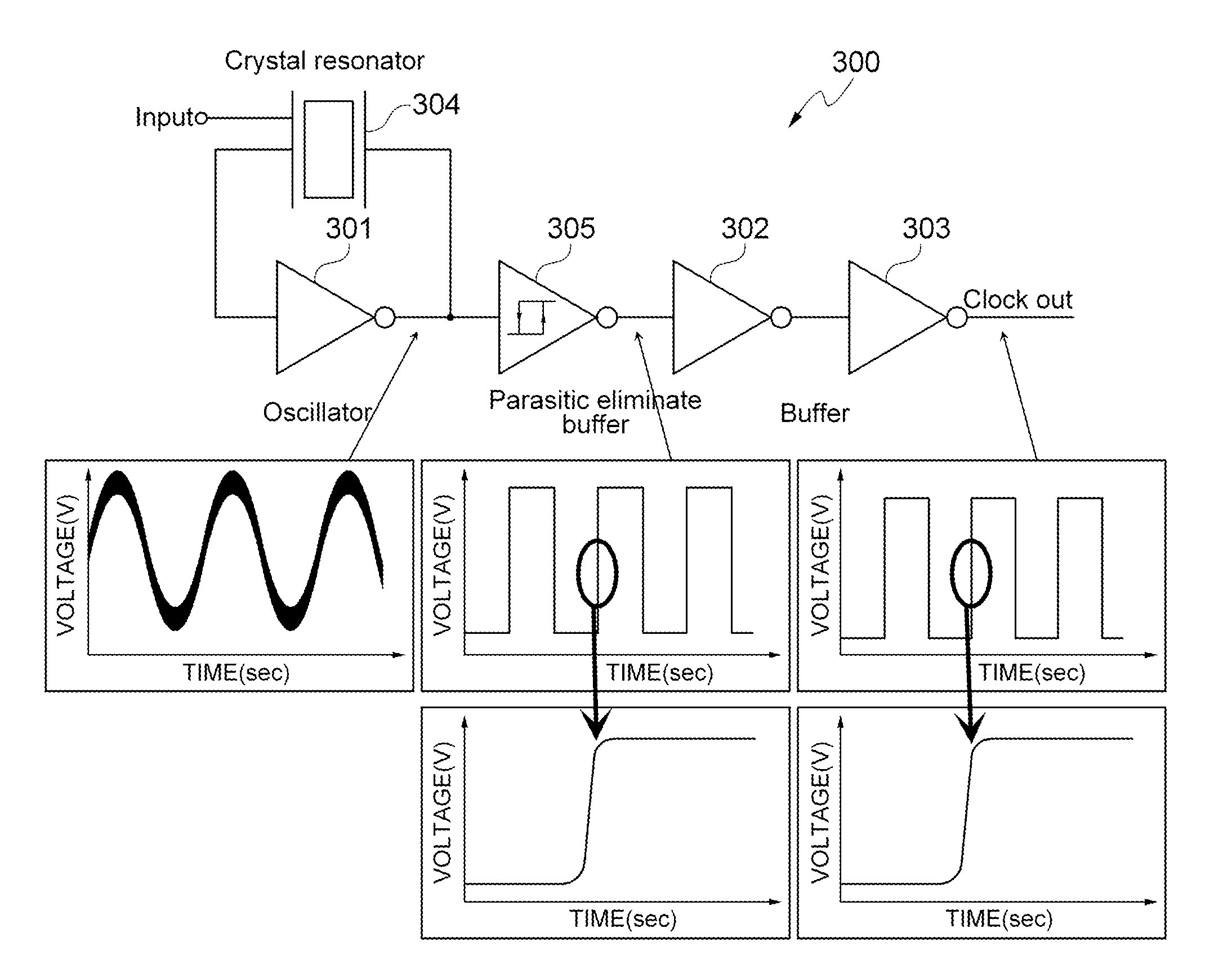
[0014]An object of the present invention is to provide a clock generating circuit having a parasitic oscillation suppressing unit capable of minimizing a malfunction due to an external influence by adding a circuit eliminating (suppressing) parasitic oscillation between an oscillator and a buffer to eliminate undesired parasitic oscillation, and a method of suppressing parasitic oscillation using the same.
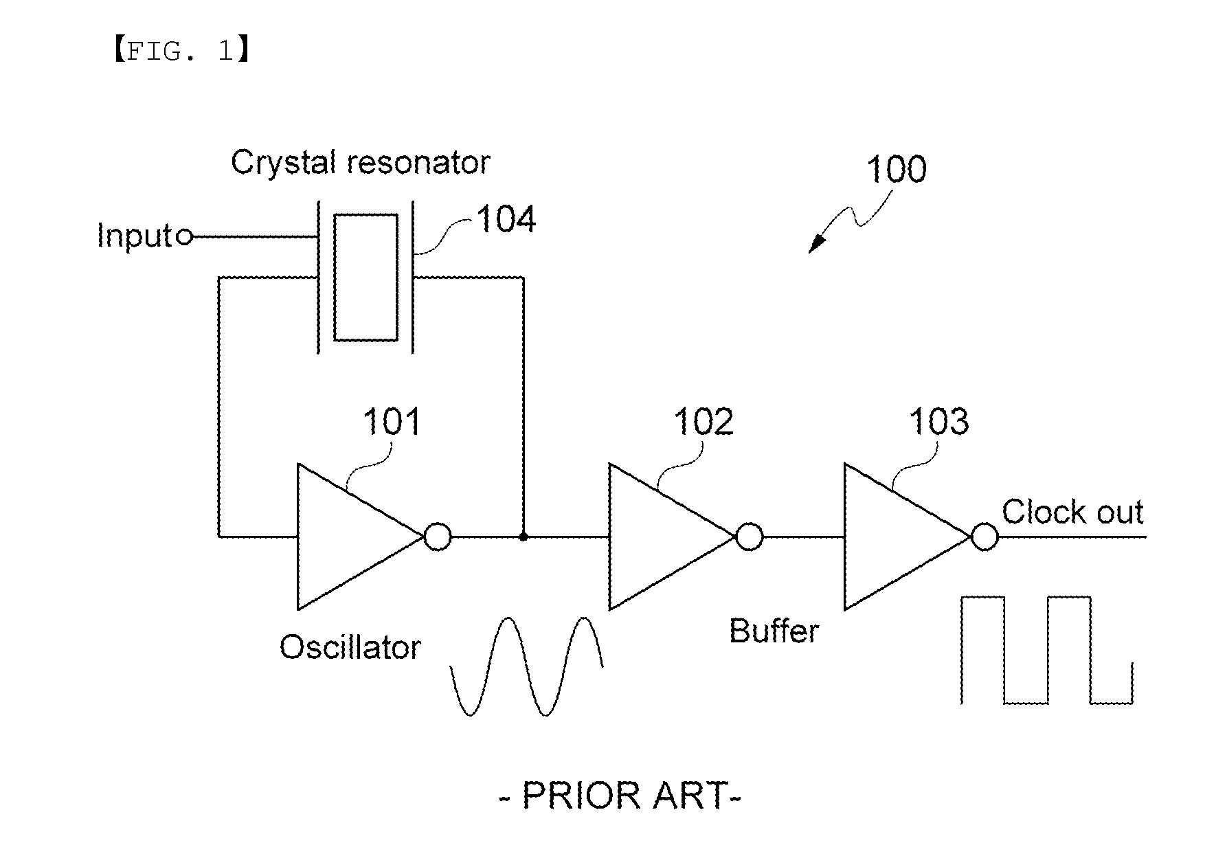
[0015]According to an exemplary embodiment of the present invention, there is provided a clock generating circuit having a parasitic oscillation suppressing unit, including: an oscillator receiving a driving signal for oscillation and oscillating a sine wave having a predetermined frequency; a first buffer receiving the sine wave output from the oscillator and outputting a square wave represented by 0 and 1; a second buffer receiving an output from the first buffer and outputting an opposite value to the received value; a crystal resonator connected in parallel with the oscillator, receiving a driving signal from the outside, resonated in a desired specific frequency band so as to generate a clock of an accurate time at a final output terminal, providing an input signal of the oscillator, and receiving an output signal fed back from the oscillator; and a parasitic component eliminating circuit installed between the oscillator and the first buffer in order to eliminate a parasitic component introduced between the oscillator and the first buffer.

Problems solved by technology

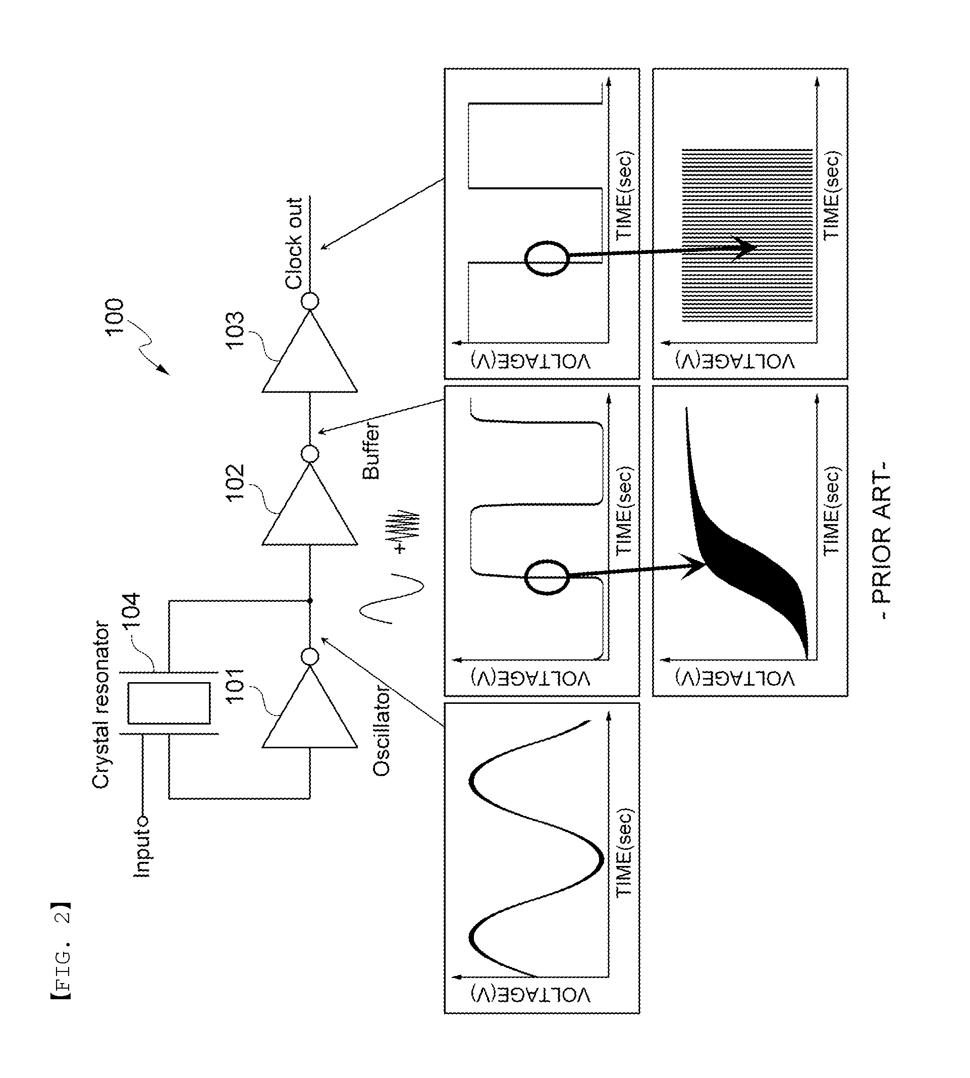
In addition, since all transistors are operated as amplifiers in these sections, even though a small signal is introduced from the outside, a clock malfunctions.
However, in this method, a large current is consumed, and it is impossible to prevent parasitic components in the case in which the parasitic components are generated in the oscillator and the buffer.
However, in this method, additional external pins are required.

Method used


Image

  • Clock generating circuit having parasitic oscillation suppressing unit and method of suppressing parasitic oscillation using the same
  • Clock generating circuit having parasitic oscillation suppressing unit and method of suppressing parasitic oscillation using the same
  • Clock generating circuit having parasitic oscillation suppressing unit and method of suppressing parasitic oscillation using the same

Examples


Embodiment Construction

[0036]Terms and words used in the present specification and claims are not to be construed as a general or dictionary meaning, but are to be construed to meaning and concepts meeting the technical ideas of the present invention based on a principle that the inventors can appropriately define the concepts of terms in order to describe their own inventions in the best mode.

[0037]Throughout the present specification, unless explicitly described to the contrary, “comprising” any components will be understood to imply the inclusion of other elements rather than the exclusion of any other elements. A term “part”, “module”, “device”, or the like, described in the specification means a unit of processing at least one function or operation and may be implemented by hardware or software or a combination of hardware and software.

[0038]Hereinafter, exemplary embodiments of the present invention will be described in detail with reference to the accompanying drawings.

[0039]FIG. 3 is a diagram sho...


PUM


Abstract

Disclosed herein are a clock generating circuit having a parasitic oscillation suppressing unit and a method of suppressing parasitic oscillation using the same. An output VDD of a parasitic component eliminating circuit is maintained in a high or low state according to the condition in which the output VDD falls from the high state to the low state and the condition in which the output VDD rises from the low state to the high state based on a threshold voltage VSPH when an input signal of the parasitic component eliminating circuit is changed from 0 to 1 and a threshold voltage VSPL when the input signal of the parasitic component eliminating circuit is changed from 1 to 0. Undesired parasitic oscillation is eliminated (suppressed) by the parasitic component eliminating circuit provided between a oscillator and a buffer.

Description

CROSS REFERENCE(S) TO RELATED APPLICATIONS[0001]This application claims the benefit under 35 U.S.C. Section 119 of Korean Patent Application Serial No. 10-2013-0037443, entitled “Clock Generating Circuit Having Parasitic Oscillation Suppressing Unit and Method of Suppressing Parasitic Oscillation Using the Same” filed on Apr. 5, 2013, which is hereby incorporated by reference in its entirety into this application.BACKGROUND OF THE INVENTION[0002]1. Technical Field[0003]The present invention relates to a clock generating circuit, and more particularly, to a clock generating circuit having a parasitic oscillation suppressing unit capable of minimizing a malfunction due to an external influence, and a method of suppressing parasitic oscillation using the same.[0004]2. Description of the Related Art[0005]Most of the integrated circuits (ICs) have used a comparatively accurate crystal oscillator in order to use a system clock or design a frequency synthesizer, or the like.[0006]Particula...

Claims


Application Information

Patent Timeline
Patent Type & Authority Applications(United States)
IPC IPC(8): H03B1/04
CPCH03B1/04H03B5/36H03B2202/012H03B2202/05
Inventor MOON, YO SUB
Owner SAMSUNG ELECTRO MECHANICS CO LTD
Why Eureka
Try Eureka