
Apparatus and method for detecting, filtering and conditioning AC voltage signals

a technology of electrical signals and filters, applied in lighting and heating apparatus, instruments, heating types, etc., can solve problems such as microprocessors or microcontrollers responding, ac voltage input signal detection interface circuits may be susceptible to errors in detecting ac voltages, and achieve the effect of minimizing microprocessor malfunction

Inactive Publication Date: 2005-04-07
EWC CONTROLS
View PDF52 Cites 2 Cited by
  • Summary
  • Abstract
  • Description
  • Claims
  • Application Information

AI Technical Summary

Benefits of technology

[0032] In accordance with another embodiment, the interface circuit includes a failsafe interface control circuit coupled between an output terminal of an external controller and the input of the at least one RS232 receiver. The failsafe interface control circuit is capable of minimizing microprocessor malfunctioning.

Problems solved by technology

If an AC voltage signal has not been conditioned appropriately (i.e., converted to a smooth DC voltage signal), electrical noise is associated with the AC input signal, there may be occasions when a microprocessor or microcontroller responds in an inappropriate manner.
For example, in an HVAC system controlled by a microcontroller, an AC voltage input signal detection interface circuit may be susceptible to errors in detecting AC voltages and converting them to DC logic voltage levels.
This may be due, in part, to spurious electrical noises received either at an input node to an interface or at an input node to the microprocessor, where under this scenario the spurious electrical noise has passed through the interface circuit to the input terminal of the microprocessor.
Spurious electrical noise can be caused by, for example, voltage dips and spikes created by an external controller's contact switches closing and opening.
Other spurious electrical noises may be caused by AC line data communications, as well as natural causes such as lightening storms.
Known microcontrollers are susceptible to errors in detecting AC voltage input signals due to these and other types of spurious noises or distortion.
These electrical noise sources impose distortion on sinusoidal AC voltage signals that not only causes errors in detecting input states but can also carry enough energy to destroy the detection circuit as well.
These known circuits, however, lack the repeatable threshold and hysteresis needed to accurately and consistently detect and decipher an AC voltage input signal from an external controller where there may be noise on the line.
Known interface circuits also cannot cope well with peak bursts of energy and other spurious noises typically associated with AC voltage sources.
Known interface circuits for microcontrollers do not commonly provide a non-distorted AC load to the AC voltage source.
Two of the most significant disadvantages include very low hysteresis and a minimum over voltage protection for the microcontroller.
In most instances, this state change is fast and not recognizable by the microprocessor to cause a problem.
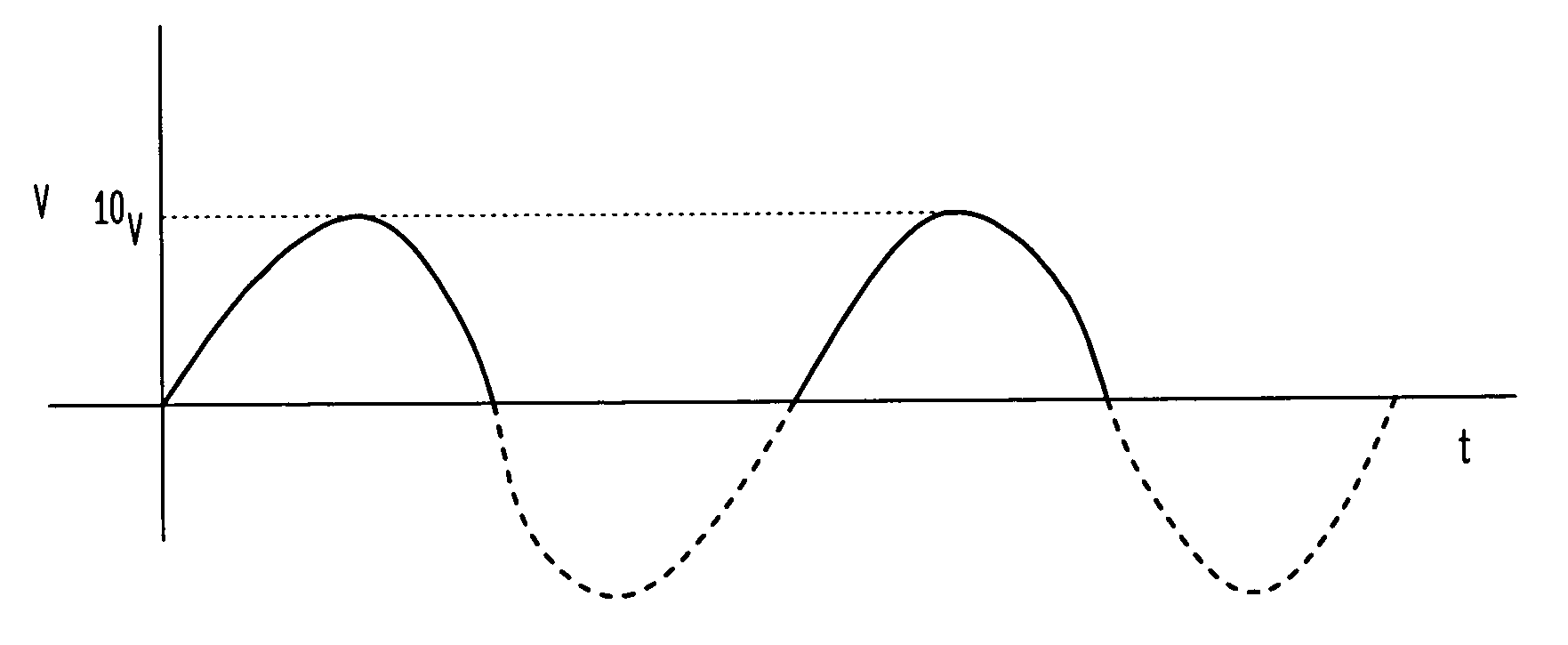
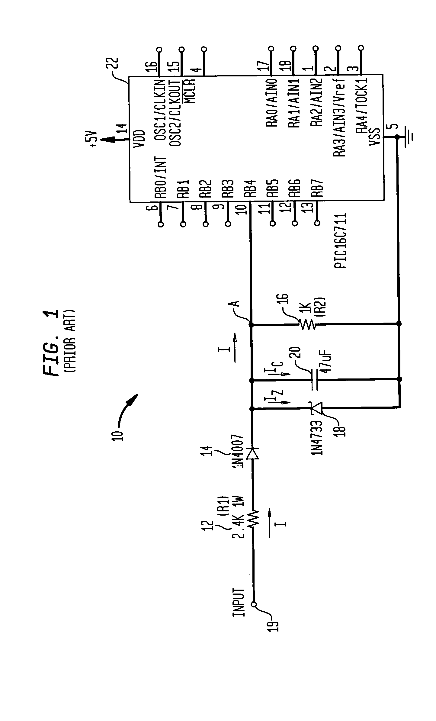
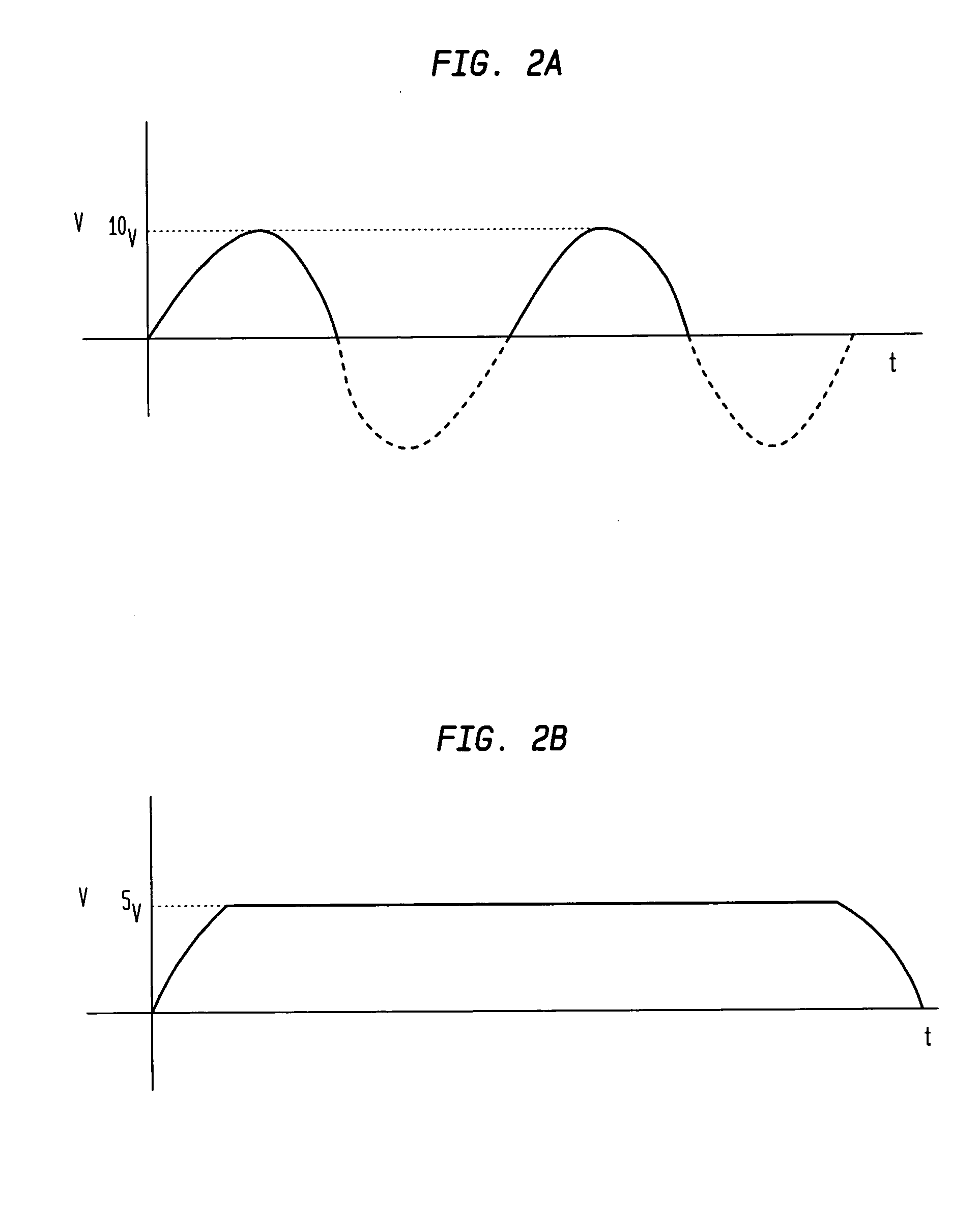
If, on the other hand, the change is relatively slow, as in the circuit depicted in FIGS. 1, 2A and 2B, perhaps because of a relatively slow discharging capacitor in an RC filter network, the microprocessor's internal input circuit may have problems interpreting the state of the signal.
However, the Zener voltage is actually affected by the current going through it.
One major disadvantage in using a Zener diode clamp to protect the microprocessor is when the microprocessor is not powered up.
As a result, the microprocessor will be damaged or malfunction.
In addition, if there is an over voltage situation, the Zener diode 18 may break down and not be able to protect the microprocessor 22 from such power surges.
Thus, another disadvantage of known microcontrollers is an inability to accurately and consistently interpret AC voltage input signals received from external controllers, such as thermostats and the like.

Method used


Image

  • Apparatus and method for detecting, filtering and conditioning AC voltage signals
  • Apparatus and method for detecting, filtering and conditioning AC voltage signals
  • Apparatus and method for detecting, filtering and conditioning AC voltage signals

Examples


Embodiment Construction

[0041] Referring now to the drawings, wherein like numerals indicate like elements, there is shown in FIGS. 3A and 3B, an AC voltage signal detection interface circuit 100 in accordance with one or more aspects of the present invention. The interface circuit 100 includes a plurality of electromechanical or electronic temperature control thermostats 102 represented by switches having contacts C1, C2 and powered by, in this example, 24 VAC. The 24 VAC is outputted from a step down transformer 104, which is coupled to a residential or commercial regulated power source (not shown) such as an outlet receptacle (not shown) providing 220 or 110 VAC RMS. That is, the 24 VAC transformer can be powered by 110 VAC or 220 VAC or any other possible line voltages. It is not important as to the source of power, except to the extent that the microcontroller circuit receives 24 VAC. Although FIGS. 3A and 3B depict thermostats as the external controllers, it should be understood by one of ordinary sk...


PUM


Abstract

An interface circuit for detecting, filtering and conditioning alternating current (AC) voltage input signals from external controllers to be received by a microcontroller. Coupled between the outputs of the external controllers and the inputs of the microcontroller of the interface circuit are RS232 receivers, which are used to detect and condition AC voltage input signals. A voltage divider having specific value resistors may be coupled between the outputs of the external controllers and the inputs of the RS232 receivers to reduce the operational voltage to a narrow detection range, the combination allowing the microcontroller to interpret the status of the AC voltage input signal.

Description

BACKGROUND OF THE INVENTION [0001] This invention relates generally to an apparatus and method for detecting, filtering and conditioning electrical signals and more particularly to an interface circuit for detecting, filtering and conditioning alternating current (“AC”) voltage input signals from external controllers, which may be coupled to a microprocessor and its associated peripherals, or a microcontroller circuit, which may include such peripherals built-in. [0002] Microprocessor-based controller circuits are known. A microcontroller is a term commonly used to describe a component that includes a microprocessor as well as built-in peripherals. Such peripherals may include but are not limited to the following: RAM, ROM, I / O AD, TimerCounter, and the like. [0003] These microcontroller circuits are often employed to detect and respond to input signals from external controllers such as, for example, manual and automatic switches, relay contacts, temperature and humidity controllers...

Claims


Application Information

Patent Timeline
Patent Type & Authority Applications(United States)
IPC IPC(8): F24F11/00G06F19/00
CPCF24F11/0009F24F11/30F24F11/88F24F11/63F24F2140/00
Inventor BAILEY, MICHAELBROWN, JOHN
Owner EWC CONTROLS
Learn More