Cutting machine with a workpiece changer

a workpiece changer and cutting machine technology, applied in the field of cutting machines, can solve the problems of requiring the operator to leave his position, and requiring a large amount of space in the prior art workpiece changer, so as to achieve the effect of less room

Active Publication Date: 2007-02-01
MIKRON AGIE CHARMILLES
View PDF15 Cites 14 Cited by
  • Summary
  • Abstract
  • Description
  • Claims
  • Application Information

AI Technical Summary

Benefits of technology

[0004] Accordingly one object of the present invention is to provide a cutting machine with a non-horizontally moving workpiece table and a workpiece tabl

Problems solved by technology

The operator therefore must leave his position during tool changing or risk exposing himself to danger.
Moreover the prior art workpiece changer requires a large amount of space and even for this reason can only be employed for cutting machines, with which a wide passage is a

Method used


Image

  • Cutting machine with a workpiece changer
  • Cutting machine with a workpiece changer
  • Cutting machine with a workpiece changer

Examples


Embodiment Construction

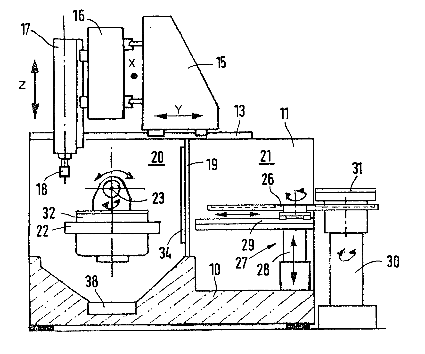
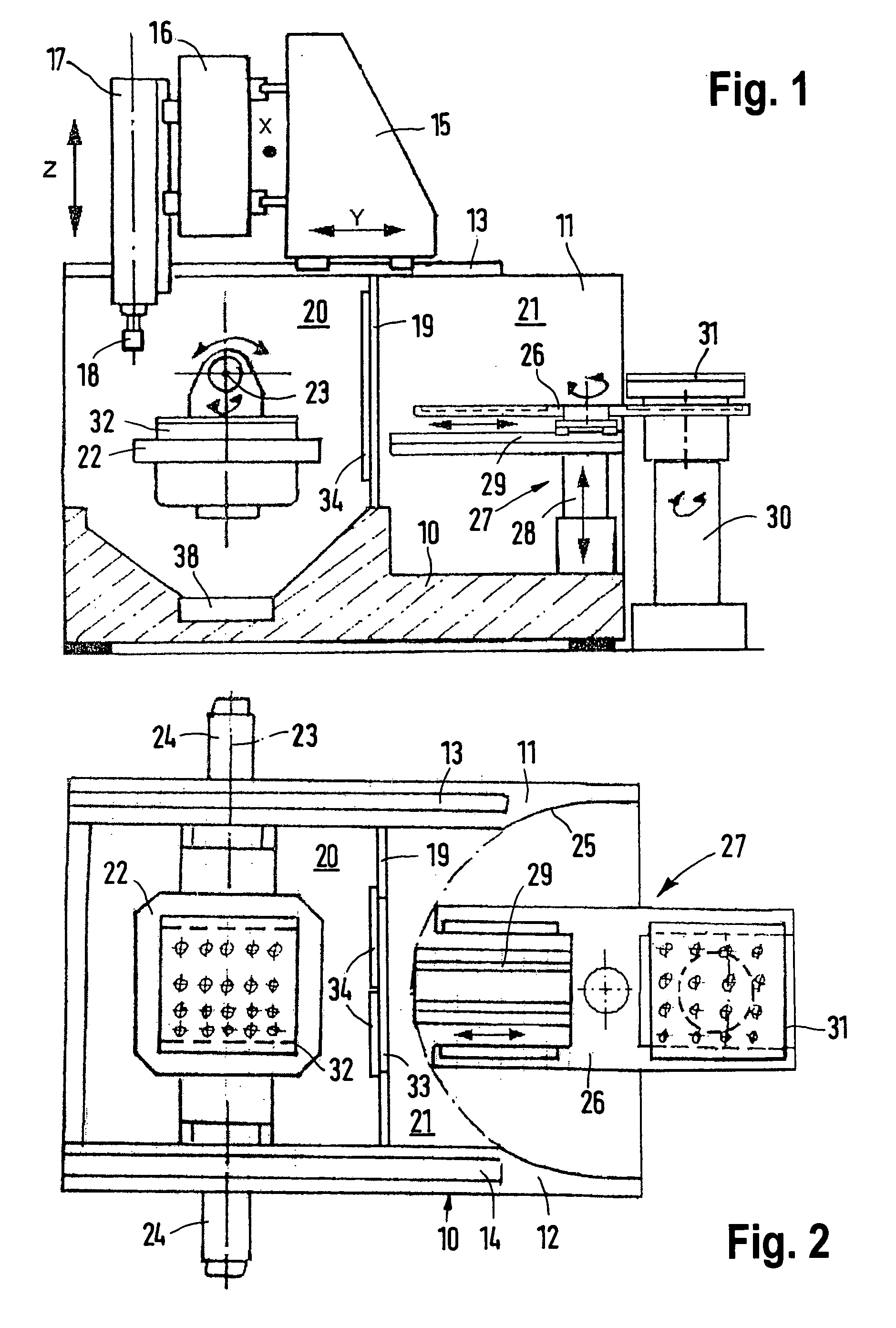
[0021] The cutting machine illustrated in FIGS. 1 and 2 as a first working example is designed in the form of a gantry machine and serves more particularly to mill and / or drill workpieces. The cutting machine possesses a bed 10 having two upright parallel and spaced apart side walls 11 and 12. On these side walls guide rails 13 and 14 are arranged for the guidance of a power driven longitudinal slide 15 able to move in the horizontal longitudinal direction Y. On this longitudinal slide 15 a transverse slide 16 runs for power driven motion in the horizontal X direction. On the transverse slide 16, in turn, a power driven tool spindle 17 is able to be shifted in the vertical Z direction and serves to drive tools 18 in rotation, which can be held in it in a interchangeable manner. A laterally arranged workpiece changer is omitted from the drawing for simplification.

[0022] The area between the side walls 11 and 12 is divided up a by transverse wall 19 into a front machining area 20 and...


PUM

PropertyMeasurementUnit
Poweraaaaaaaaaa

Abstract

A cutting machine comprises a workpiece changer possessing a receiving element for the workpieces and/or workpiece palettes, said receiving element being able to be pivoted about a vertical axis and to be linearly shifted in a plane normal to such axis. At least one slide arrangement is able to be power driven in the two horizontal directions for a tool spindle and is adapted to run on two parallel side walls of the cutting machine designed in the form of a gantry machine. The intermediate space between the side walls is divided by a transverse wall or by door, which during workpiece machining is closed and during the workpiece changing operation is at least partly open, into a front machining area and a rear supply area, the radius of pivoting of the receiving element, engaging a workpiece or a workpiece palette, extending at least partly into a supply area. Accordingly a person minding or controlling the functioning cutting machine is not hampered by workpiece changing.

Description

BACKGROUND OF THE INVENTION [0001] The invention relates to a cutting machine comprising a workpiece changer for shifting the workpieces and / or workpiece palettes to be processed between at least one transfer site outside the cutting machine, and a horizontally immobile workpiece table of the cutting machine, said workpiece changer possessing a receiving element for the workpieces and / or workpiece palettes, said receiving element being able to be pivoted about a vertical axis and to be linearly shifted in a plane normal to such axis, and a tool spindle arranged on a slide arrangement able to be power driven at least in the two horizontal directions. THE PRIOR ART [0002] In the case of such a cutting machine described in the U.S. Pat. No. 4,373,840 the supply of the workpiece palettes takes place from the front, that is to say from that side at which an operator controls and / or minds the machining operation. The operator therefore must leave his position during tool changing or risk ...

Claims


Application Information

Patent Timeline
IPC IPC(8): B23Q7/00
CPCB23Q1/012B23Q1/66Y10T409/308288Y10T409/30392Y10T409/306048Y10T29/5196
Inventor BERNHARD, FRANZ-XAVERSCHWORER, TOBIAS
Owner MIKRON AGIE CHARMILLES
Why Eureka
Try Eureka