Nose hair cutter

a cutting tool and nose technology, applied in the direction of metal working tools, etc., can solve the problems of deteriorating cutting sharpness and inability to reliably cut, and achieve the effects of enhancing cutting sharpness, less prone to pieces being blocked, and enhancing assembly properties

Active Publication Date: 2007-02-01
MATSUSHITA ELECTRIC WORKS LTD
View PDF8 Cites 7 Cited by
  • Summary
  • Abstract
  • Description
  • Claims
  • Application Information

AI Technical Summary

Benefits of technology

[0009] According to the present invention, since the cutting edge of the inner blade is located rearward of the main body in the inner blade insertion hole in the rotational direction. With this configuration, when the cutting edge rotates while being in contact with the inner peripheral surface of the slit outer blade by the pushing force of the spring, the cutting edge does not fall forward in the rotational direction. Therefore, no gap is generated between the cutting edge and the inner peripheral surface of the slit outer blade and thus, pieces of nose hair entering into the inner peripheral surface from the slit groove of the slit outer blade can be cut reliably, a

Problems solved by technology

Thus, there is a problem that pieces of nose hair that enter the inner peripheral surface 3a from a s

Method used


Image

  • Nose hair cutter
  • Nose hair cutter
  • Nose hair cutter

Examples


Embodiment Construction

[0020] Embodiments of the present invention will be explained below with reference to the accompanying drawings.

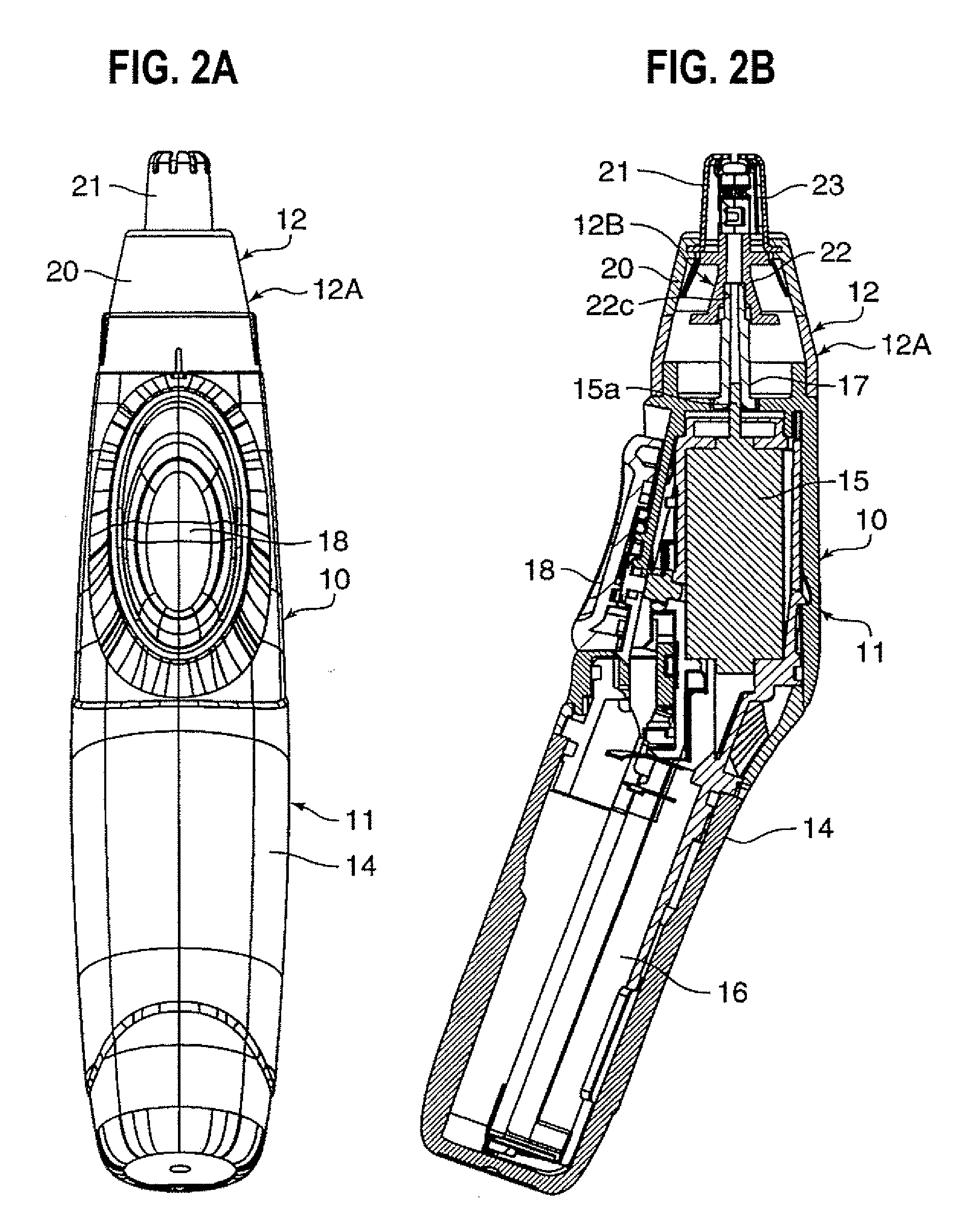
[0021]FIG. 2A is a front view of a nose hair cutter 10, and FIG. 2B is a side sectional view of the nose hair cutter 10. The nose hair cutter 10 includes a main body assembly (main body block) 11, and a blade assembly (blade block) 12 detachably amounted on an upper portion of the main body assembly 11.

[0022] An electric motor 15 and a dry battery accommodating chamber 16 in which a dry battery for driving the electric motor 15 are provided in a housing 14 of the main body assembly 11. A joint member 17 is press fitted and fixed to an output shaft 15a of the electric motor 15. The front surface of said housing 14 is provided with a push button switch 18 for turning the electric motor 15 ON and OFF.

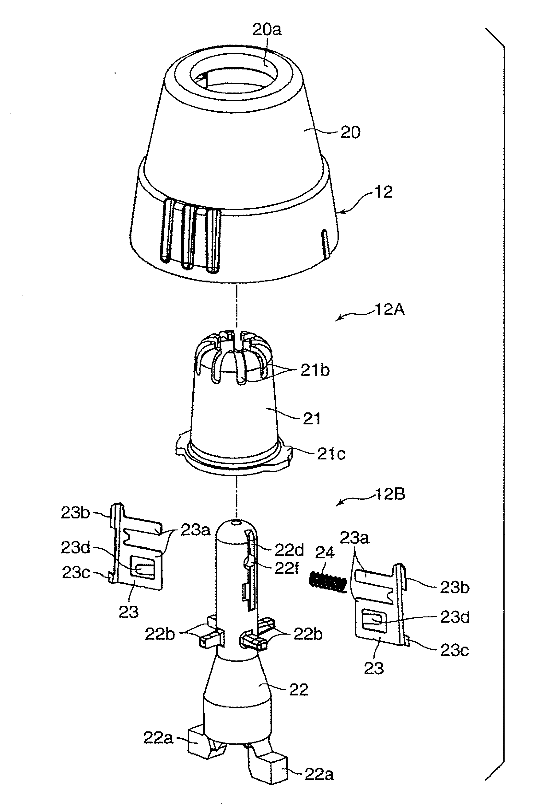
[0023] As shown in FIGS. 3 to FIGS. 7A, 7B, and 7C, the blade assembly 12 includes an outer blade block 12A and an inner blade block 12B. The outer blade block 12A includes an...


PUM


Abstract

A main body of an inner blade is inserted into an inner blade insertion hole of an inner blade frame such that the main body can extend and retreat, a tip end cutting edge is pushed by a spring such that it comes into contact with an inner peripheral surface of a slit outer blade, the main body of the inner blade projecting outward from the inner blade insertion hole is bent rearward in a rotational direction, and the cutting edge of the inner blade is located rearward of the main body in the inner blade insertion hole in the rotational direction. With this configuration, the cutting edge does not fall forward in the rotational direction, and no gap is generated between the cutting edge and the inner peripheral surface of the slit outer blade.

Description

CROSS REFERENCE TO RELATED APPLICATIONS [0001] This application is based upon and claims the benefit of priority from prior Japanese Patent Application P2005-216214 filed on Jul. 26, 2005; the entire contents of which are incorporated by reference herein. BACKGROUND OF THE INVENTION [0002] The present invention relates to a nose hair cutter for cutting nose hair. [0003] As a conventional nose hair cutter, as disclosed in Japanese Patent No. 3536345 (Patent document 1, hereinafter) there is a known nose hair cutter including a slit outer blade and an inner blade that is rotated, in which nose hair that enters an inner peripheral surface of the slit outer blade is cut by the inner blade. [0004] According to such a nose hair cutter, as shown in FIG. 1, a main body la of an inner blade 1 is inserted into an inner blade insertion hole 2a of an inner blade frame 2 such that the inner blade 1 can expand and retreat, a tip end cutting edge lb is pushed by a spring (not shown) (pushing direc...

Claims


Application Information

Patent Timeline
IPC IPC(8): B26B19/14
CPCB26B19/148B26B19/00
Inventor MORISUGI, KAZUHIROIKUTA, TOSHIOKOSUGI, YOSHIMICHI
Owner MATSUSHITA ELECTRIC WORKS LTD
Why Eureka
Try Eureka