Flow stability in massively parallel cryogenic vaporizers

a cryogenic vaporizer and massive parallel technology, applied in indirect heat exchangers, lighting and heating apparatus, container discharge methods, etc., can solve the problems of difficult to develop the wide varying flows through each element, and achieve the effect of reducing the tendency to maldistribute flow

Inactive Publication Date: 2007-02-01
CRYOQUIP
View PDF9 Cites 5 Cited by
  • Summary
  • Abstract
  • Description
  • Claims
  • Application Information

AI Technical Summary

Benefits of technology

[0003] A major object of the invention is to provide a method and means for mitigating the effects of the tendency to maldistribute flow in cryogenic vaporizers. While the invention has special application to massively parallel (involving hundreds or thousands of parallel paths) ambient air vaporizers, the invention is equally applicable to other parallel flow path vaporizers.

Problems solved by technology

If the restrictor produces a pressure drop at least equal to the normal pressure drop in an element, it is very difficult to develop the wide varying flows through each element.
While orifices can often be used as restrictors, they may cause problems in low flow cases where the opening becomes so small that it is subject to plugging from debris or contaminates in the vaporizing fluid.

Method used


Image

  • Flow stability in massively parallel cryogenic vaporizers
  • Flow stability in massively parallel cryogenic vaporizers
  • Flow stability in massively parallel cryogenic vaporizers

Examples


Embodiment Construction

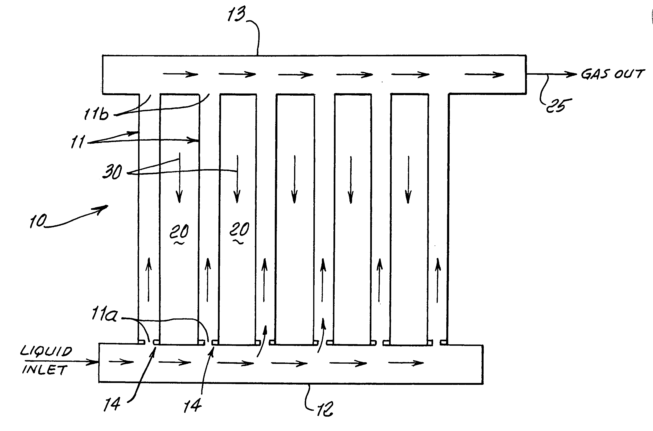
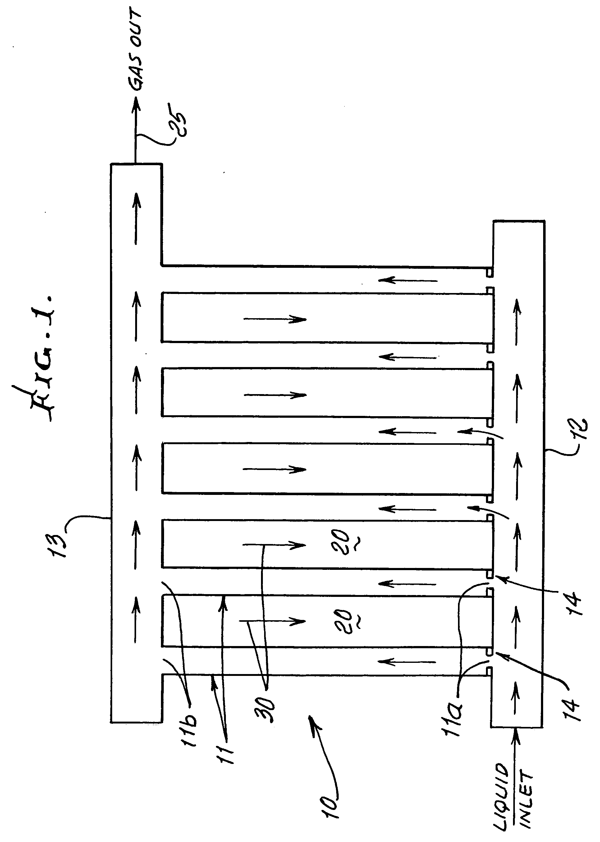
[0020] In FIG. 1, a vaporizer 10 has like multiple parallel warming ducts 11, with inlets 11a for receiving cryogenic liquid from a supply manifold 12, and outlets 11b for discharging warmed and vaporized cryogenic fluid or gas into a collection manifold 13. Warming gas such as ambient air flows at 30 through or along spaces 20 between the ducts.

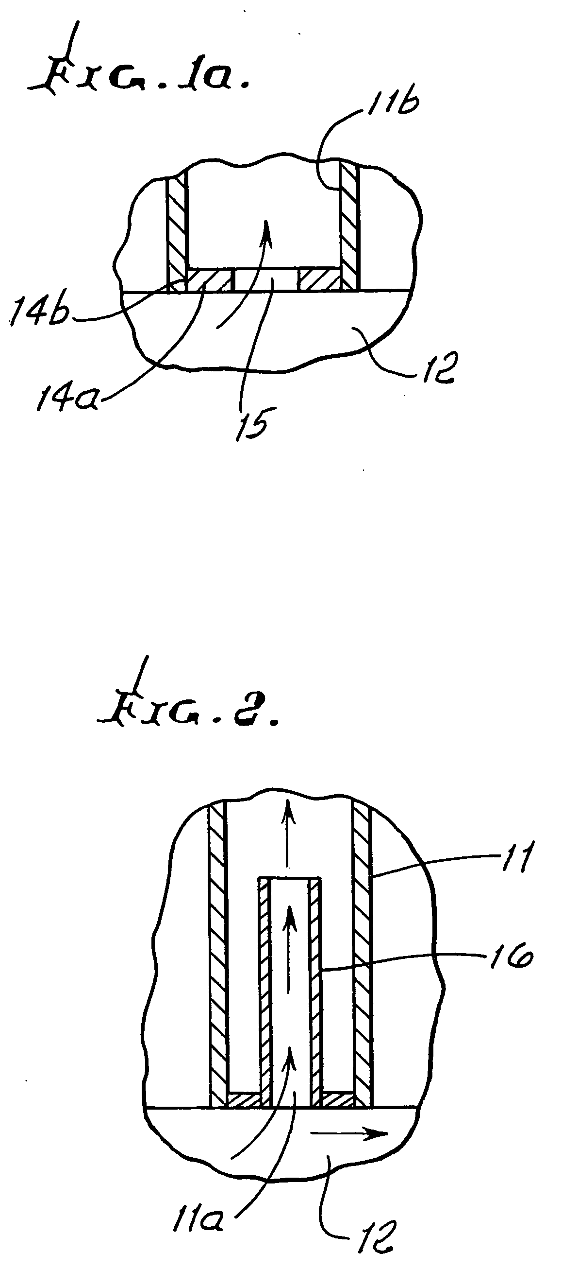
[0021] Flow restrictors 14 are installed at the duct entrances, and may take the form as seen in FIG. 1a showing an annulus 14a, with outer extent 14b circumferentially attached to the inner wall 11b of a duct 11, at its lower end entrance to the duct. The restrictor may provide an orifice 15 of smaller diameter or cross dimensions d1 than the bore diameter or cross dimension d2 of the duct. Flow passing through the orifice undergoes throttling to a reduced pressure level. One highly advantageous mode of operation is to configure the orifice so that the pressure drop through the orifice 15 is at least equal to the pressure drop occurring al...


PUM


Abstract

Cryogenic vaporization apparatus with multiple ducts each having an inlet to receive cryogenic fluid for vaporization, and an outlet to discharge vaporized fluid to a common discharge collection manifold, there being spaces between the ducts to pass warming fluid, for warming the ducts, and flow restrictors at or proximate the inlets to produce pressure drops in the flow in the ducts, and acting to reduce flow instabilities in the manifold.

Description

BACKGROUND OF THE INVENTION [0001] This invention relates generally to operation of cryogenic vaporizers, and more particularly to enhancement of flow stability in such vaporizers. [0002] Cryogenic liquids (fluids) normally require heat addition (to produce vaporization) in order to convert cold gases into usable warm gases. The devices used to perform this are referred to as vaporizers. They can use any heat source, examples being ambient air, steam, warm water, seawater, electricity, fuel fired, and waste heat. When using parallel heat transfer elements (for example tubes) a stability problem arises due to the nature of the heat addition. When a heat transfer element is functioning normally, the first portion of the element (tube) is in the boiling zone and cold. As the cryogen leaves the boiling zone, it begins to accumulate superheat until it reaches the discharge temperature. Most of the pressure drop inside the tube is associated with the higher velocity of warmer gas. In a pa...

Claims


Application Information

Patent Timeline
Patent Type & Authority Applications(United States)
IPC IPC(8): F25B9/00F17C9/02
CPCF17C9/02F17C2270/0136F25B39/028F28D1/053F28D2021/0033F28D2021/0064F28D2021/0071F17C2221/033F17C2223/0161F17C2223/033F17C2225/0123F17C2225/036F17C2227/0311F17C2227/0393F17C2270/0123F17C2265/05
Inventor BILLMAN, PATRICK
Owner CRYOQUIP
Why Eureka
Try Eureka