Remotely actuated beveling systems for a miter saw

a technology of remote action and miter saw, which is applied in the field of miter saws, can solve the problems of ineffective and awkward arrangement of difficulty in reaching around the back of the miter saw to lock the bevel angle locking system, etc., and achieves effective and efficient bevel. , the effect of reducing the difficulty of reaching around the back of the miter saw

Inactive Publication Date: 2007-02-01
BLACK & DECKER INC
View PDF10 Cites 10 Cited by
  • Summary
  • Abstract
  • Description
  • Claims
  • Application Information

AI Technical Summary

Benefits of technology

[0010] This invention seeks to alleviate the awkwardness and inconvenience of having to reach around to the back of a miter saw to actuate the bevel angle locking system. This invention also seeks to alleviate the awkwardness and inconvenience of having to reach around to the back of a miter saw to override the bevel angle adjustment assistance system. This invention also proposes an effective and efficient bevel angle adjustment assistance system where each of the several preset bevel angles can be fine tuned in one operation.
[0011] In one embodiment, a miter saw comprises a base assembly, a saw unit having a saw blade, and a saw support assembly rotatably mounted to the base assembly, the saw support assembly supporting the saw unit and pivoting the saw unit to plunge the saw blade into a workpiece laying on the base assembly, the saw support assembly rotating relative to the base assembly to adjust the bevel angle of the saw blade. A pin has a first end anchored to the saw support assembly and extends from the first end toward the base assembly. The miter saw further comprises a remote actuator for locking together and preventing relative rotation between the saw support assembly and the turntable, the remote actuator is operatively connected to the pin at a position opposite the first end. When the remote actuator is actuated the pin is tensioned, the tensioned pin pulling the saw support assembly towards the base assembly to help prevent relative rotation of the saw support assembly and the turntable.
[0012] In another embodiment, a method of adjusting and locking the bevel angle of a miter saw comprises the steps of rotating a saw support assembly mounting a saw unit to a desired bevel angle, tensioning a pin which extends between the saw support assembly and a base assembly by pulling the pin in the direction of the base assembly, and using the tension in the pin to create compressive force between the saw support assembly and the base assembly, the compressive force resulting in friction which helps prevent the saw support assembly from rotating relative to the base assembly.
[0015] In another embodiment, a miter saw comprises a base assembly, a saw unit having a saw blade, and a saw support assembly rotatably mounted to the base assembly, the saw support assembly supporting the saw unit and pivoting the saw unit to plunge the saw blade into a workpiece laying on the base assembly, the saw support assembly rotating relative to the base assembly to adjust the bevel angle of the saw blade. A pin extends between the saw support assembly and the base assembly. A lever is operatively connected to the pin wherein when the lever is pivoted, the lever pulls on the pin to tension the pin, the tensioned pin causing compressive force to be increased between the saw support assembly and the base assembly to help prevent relative rotation between the saw support assembly and the base assembly.

Problems solved by technology

Reaching around to the back of the miter saw can be awkward, especially on large miter saws.
As can be seen, having to reach around the miter saw to actuate the bevel angle locking system is an inefficient and awkward arrangement.
During such tasks, the difficulty in reaching around the back of the miter saw to lock the bevel angle locking system is particularly acute.
This can be awkward, especially if the miter saw is relatively large or the actuator is not placed in an easy to reach location.
If the manufacturer is to initially fine tune each of the preset bevel angles as part of the manufacturing assembly process, the multiple separate adjustments which are required can be laborious and as a result quite expensive for the manufacturer.
This cost can be especially significant when there are three or more preset bevel angles.
The required multiple separate adjustments for fine tuning the preset bevel angles can be burdensome for the user, too.

Method used


Image

  • Remotely actuated beveling systems for a miter saw
  • Remotely actuated beveling systems for a miter saw
  • Remotely actuated beveling systems for a miter saw

Examples


Embodiment Construction

[0028] The preferred embodiments of this invention are directed to, among other things, a remotely actuated bevel angle locking system, a remote override actuator for a bevel angle adjustment assistance system, and a beveling detent system. The principles of the invention will be described through their application, i.e., by showing how a particular type of bevel angle locking system can be remotely actuated and how a particular type of bevel angle adjustment assistance system can be overridden with a remote actuator. However, those of ordinary skill in the design of miter saws and power tools will be able to readily apply these principles to remotely actuate other types of bevel angle locking systems and remotely override other types of bevel angle adjustment assistance systems.

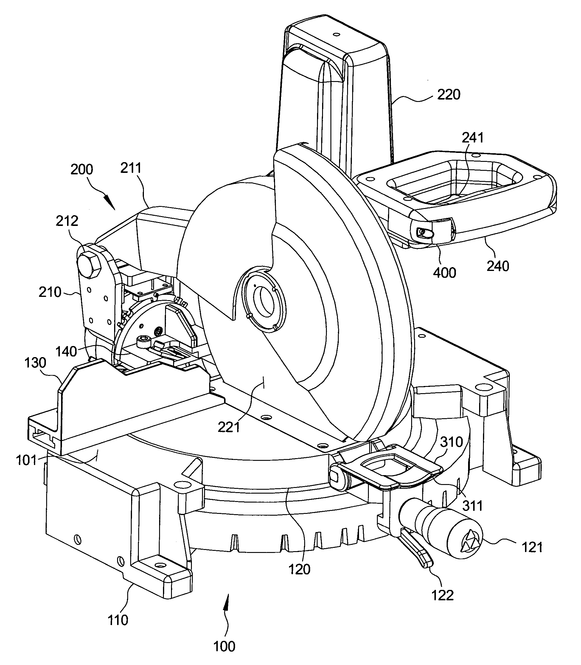
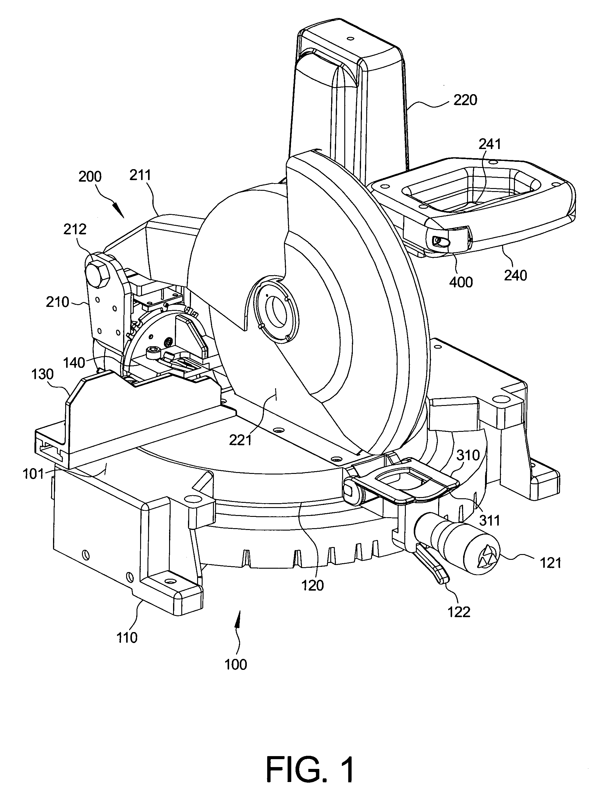
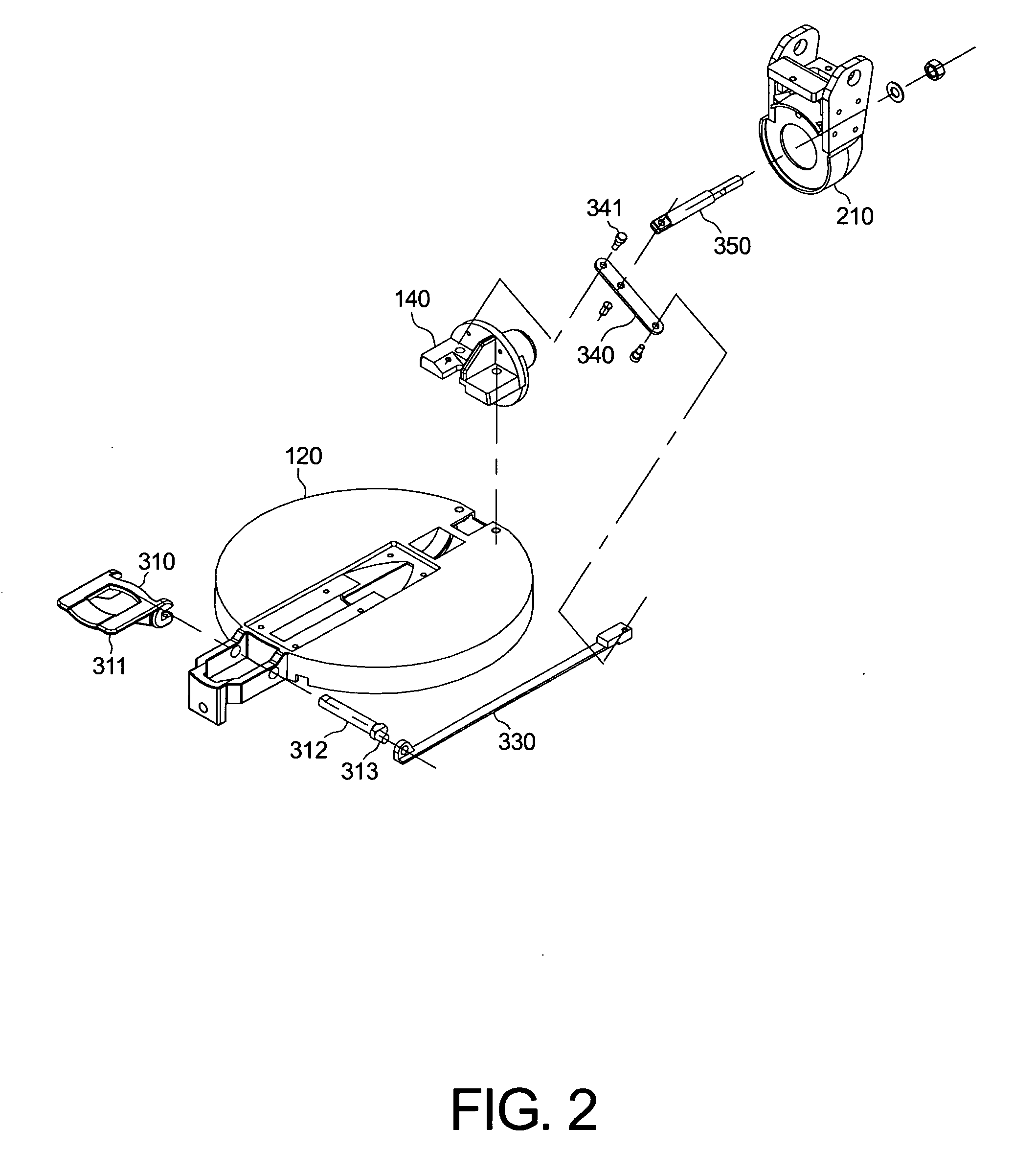
[0029] An illustrative embodiment of one miter saw is shown in FIGS. 1-13. With reference first to FIG. 1, a base assembly 100 can include a base 110 and a turntable 120. The turntable 120 is rotatably supp...


PUM

PropertyMeasurementUnit
bevel angleaaaaaaaaaa

Abstract

A miter saw has a remotely actuated bevel angle locking system and a bevel angle adjustment assistance system with a remote override actuator so that the user does not need to reach around to the back of the miter saw to adjust the bevel angle. The remote actuator for the bevel angle locking system can be provided on the front of the miter saw's turntable to form a suite of actuators with the miter lock and miter detent override lever. The remote override actuator for the bevel angle adjustment assistance system can be provided on the handle in proximity to the power switch. Also disclosed is a bevel angle adjustment assistance system in which each of the preset bevel angles can be fine tuned simultaneously and which exhibits other advantages.

Description

PRIORITY DATA [0001] This application is a Divisional of U.S. patent application Ser. No. 10 / 211,593 filed on Aug. 5, 2002, which claims priority to U.S. Provisional Application No. 60 / 354,942 filed on Feb. 11, 2002. The entire contents of these applications are incorporated herein by reference.BACKGROUND OF THE INVENTION [0002] The field of this invention is miter saws. In a compound miter saw, the miter angle and bevel angle of the saw blade can be adjusted independent of one another, or simultaneously to make compound angle cuts. Rotating the saw blade about a vertical miter axis adjusts the miter angle. The complement of the included angle that the saw blade makes with the miter saw's fence customarily represents the miter angle. Typically, a turntable is rotatably mounted on the miter saw's base to permit the miter angle adjustment. [0003] Rotating the saw blade about a horizontal beveling axis adjusts the bevel angle. The beveling axis preferably lies in approximately the same...

Claims


Application Information

Patent Timeline
Patent Type & Authority Applications(United States)
IPC IPC(8): B23D45/04B26D1/14B27B5/29
CPCB27B5/29B23D45/044Y10T83/8773Y10T83/7726Y10T83/7705Y10T83/05Y10T83/7697Y10T83/7788
Inventor CARROLL, CRAIG ALLENSTAFFORD, BRENT EDWARD
Owner BLACK & DECKER INC
Why Eureka
Try Eureka