Compact duct system incorporating moveable and nestable baffles for use in tools used to process microelectronic workpieces with one or more treatment fluids

a technology of microelectronic workpieces and duct systems, applied in the field of tools, can solve the problems of inability to use a single duct in all instances, treatment fluids may be too reactive in the presence of other treatment materials, and conventional approaches suffer serious drawbacks, and achieve the effect of reducing cross-contamination

Active Publication Date: 2007-02-01
FSI INTERNATIONAL INC
View PDF57 Cites 46 Cited by
  • Summary
  • Abstract
  • Description
  • Claims
  • Application Information

AI Technical Summary

Benefits of technology

[0008] The present invention provides a novel duct system for use in tools in which microelectronic workpieces are treated with treatment fluids, including liquids, gases, fluidized solids, dispersions, combinations of these and the like. The ducts are used to capture the various treatment fluids for recycling, discarding, or other handling. Different treatment fluids can be recovered in different, independent ducts to minimize cross-contamination and / or to use unique capture protocols for different fluids.
[0014] In another aspect, the present invention relates to an apparatus for processing a microelectronic workpiece. The apparatus includes a processing chamber in which the workpiece is positioned during a process. A barrier structure overlies and covers the workpiece in a manner effective to help provide a tapering flow channel proximal to a major surface of the workpiece.
[0016] In another aspect, the present invention relates to an apparatus, comprising a processing chamber in which the workpiece is positioned during a process. A barrier structure overlies and covers the workpiece in a manner effective to help provide a tapering flow channel proximal to a major surface of the workpiece that tapers in a radially outward direction relative to said surface. The barrier structure is controllably moveable through a range of motion including a first position in which the processing chamber is sufficiently open to allow workpiece transfer to and from the processing chamber and a second position in which the barrier structure helps to guide at least one material flowing over said major surface.
[0018] In another aspect, the present invention relates to a nozzle device comprising an annular body having a lower surface that is angled so as to help define a tapering flow channel over a workpiece surface when the annular body is positioned over the workpiece surface. The annular body comprises an inner periphery defining a central pathway that provides egress between a volume above the annular body and a volume below the annular body. An arm structure is coupled to the annular body and extends generally across the central pathway in a manner effective to help define first and second pathway portions. At least a first, independent array of nozzles is integrated with the annular body in a manner such that the first array extends at least partially along the arm structure and a first radius of the annular body in a manner effective to dispense one or more processing materials downward onto the workpiece surface. At least one independent nozzle is integrated into the central arm in a manner effective to dispense one or more processing materials downward onto a central portion of the workpiece. At least one independent nozzle is positioned to dispense one or more processing materials onto the workpiece from a flow path that extends through at least one of the central flow pathway portions.
[0020] In another aspect, the present invention relates to an apparatus for processing a microelectronic workpiece. The apparatus includes a processing chamber in which the workpiece is positioned during a process and a moveable member comprising a tube portion having a through bore. The moveable member is positioned over the workpiece and is moveable relative to a major surface of the workpiece. At least one independent nozzle structure is physically coupled to the moveable member such that movement of the moveable member allows the relative spacing between the major surface of the workpiece and the nozzle structure to be controllably adjusted. At least a portion of at least one fluid supply pathway in the through bore of the tube portion is fluidly coupled to the at least one independent nozzle structure and workpiece.

Problems solved by technology

However, using a single duct like this is not desirable in all instances.
For example, some treatment fluids may be too reactive in the presence of other treatment materials.
This conventional approach suffers from serious drawbacks.
The stacked ducts make high-density tool packaging more difficult.
The different ducts may also be subject to cross-contamination because they are always open to the workpiece and / or exhaust levels are not individually controlled.
Some conventional duct systems also may not have the capability to separate the liquid and gas constituents of an exhaust stream.
In some tools in which the duct structures themselves are moveable, drain and exhaust connections to external plumbing must also move, thereby adding undue complexity to tool design, manufacture, use, and service.

Method used


Image

  • Compact duct system incorporating moveable and nestable baffles for use in tools used to process microelectronic workpieces with one or more treatment fluids
  • Compact duct system incorporating moveable and nestable baffles for use in tools used to process microelectronic workpieces with one or more treatment fluids
  • Compact duct system incorporating moveable and nestable baffles for use in tools used to process microelectronic workpieces with one or more treatment fluids

Examples


Embodiment Construction

[0065] The embodiments of the present invention described below are not intended to be exhaustive or to limit the invention to the precise forms disclosed in the following detailed description. Rather the embodiments are chosen and described so that others skilled in the art may appreciate and understand the principles and practices of the present invention. While the present invention will be described in the specific context of fluid based microelectronic substrate cleaning systems, the principles of the invention are applicable to other microelectronic processing systems as well.

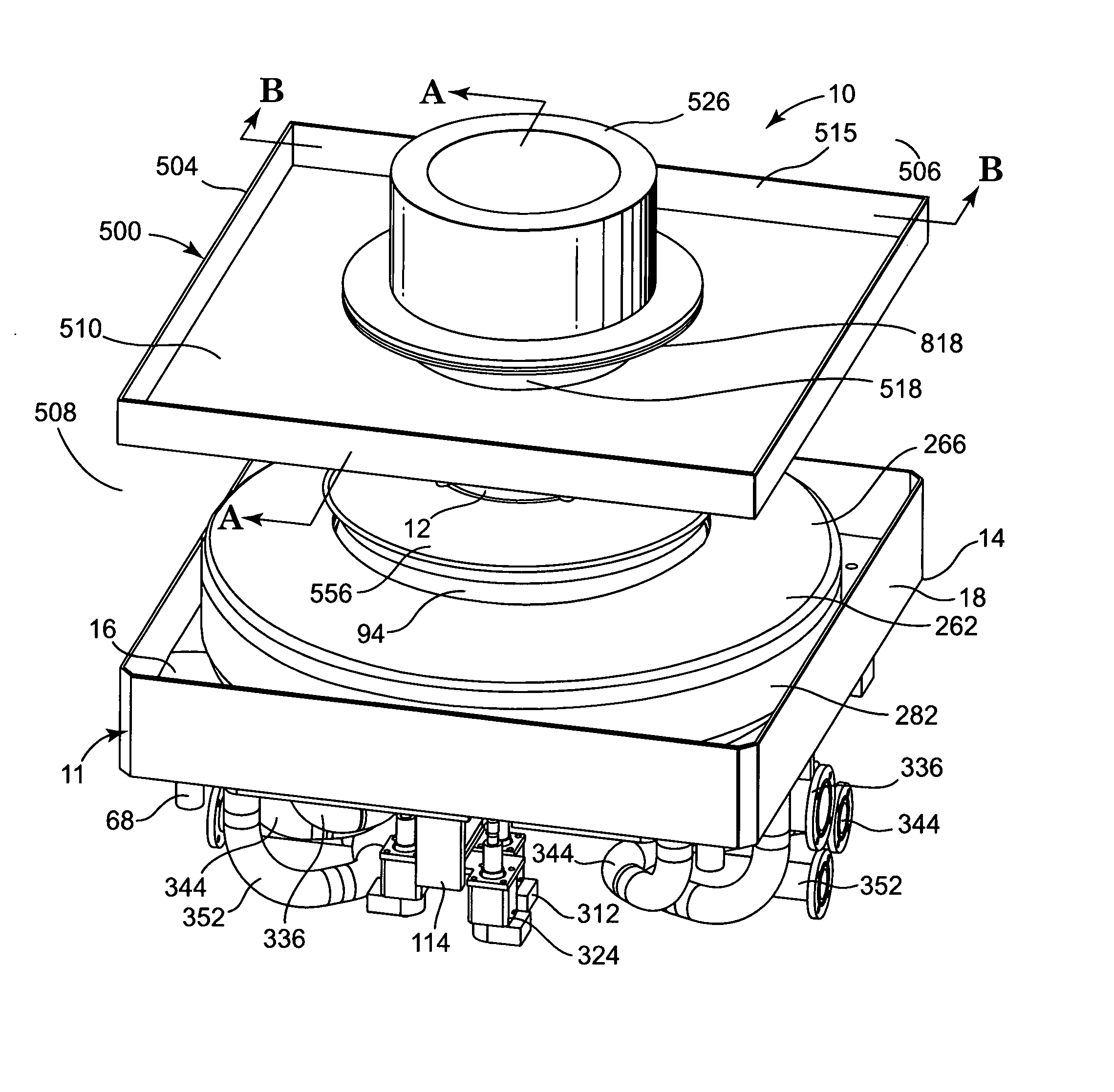
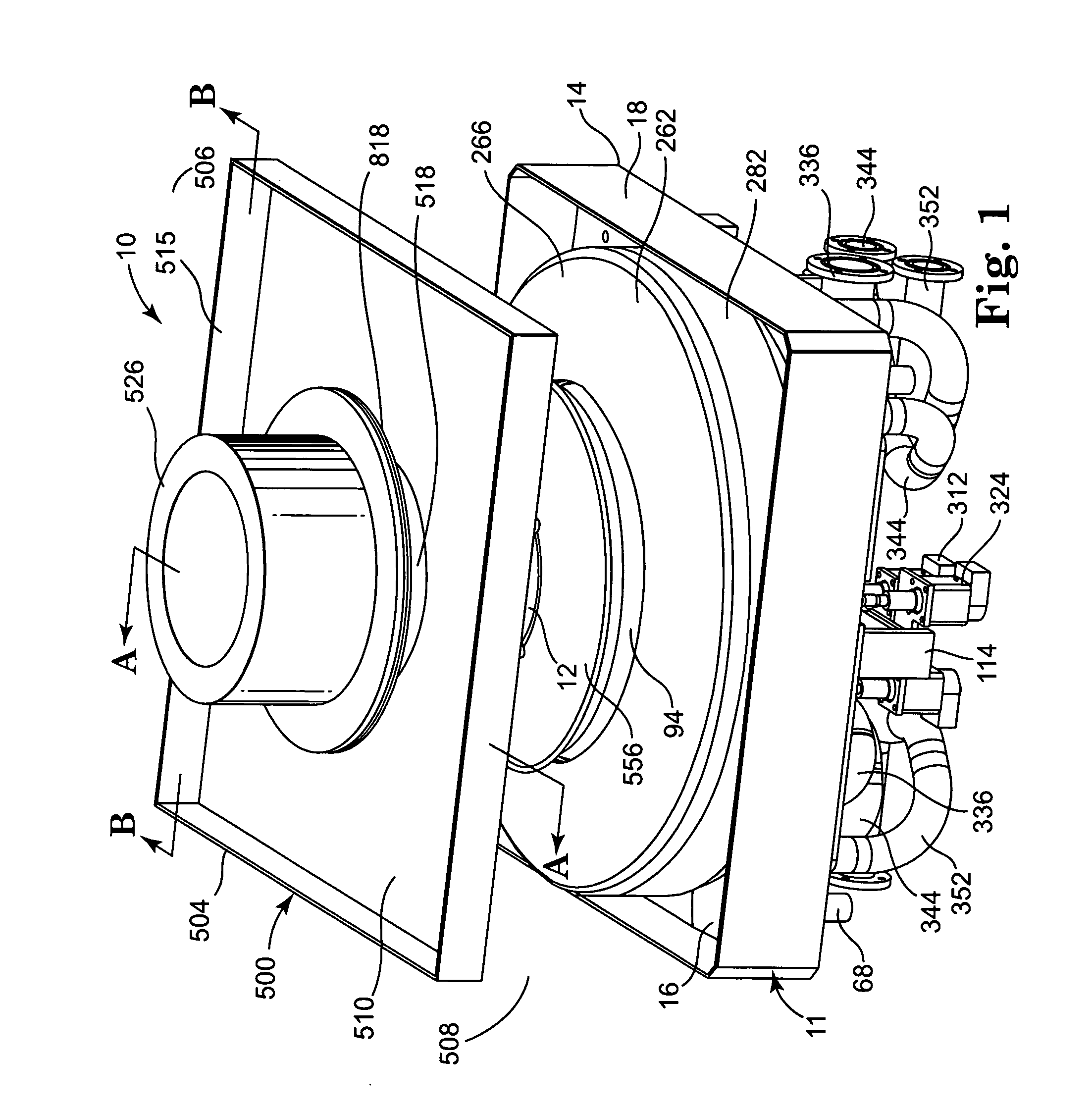
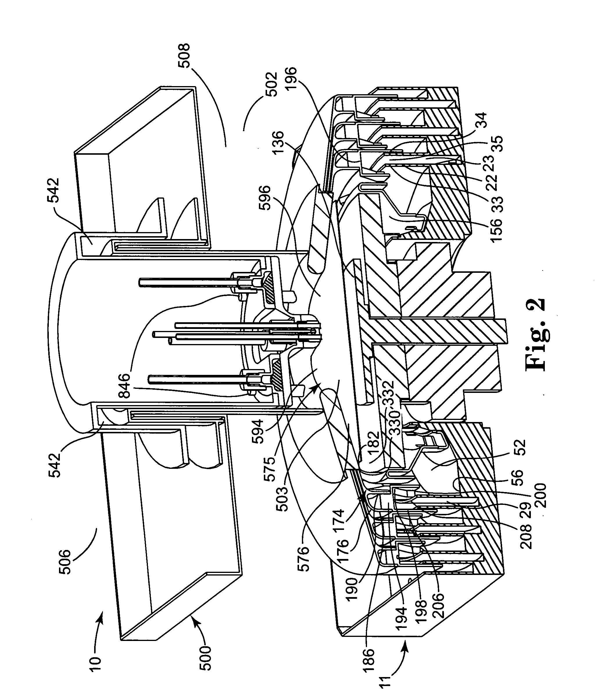
[0066]FIGS. 1 through 38 show an illustrative tool 10 that incorporates principles of the present invention. For purposes of illustration, tool 10 is of the type in which a single workpiece 12 is housed in the tool 10 at any one time and subjected to one or more treatments in which liquid(s) and / or gas(es) are caused to contact the workpiece 12. In the microelectronics industry, for instance, tool 10 may...


PUM


Abstract

Apparatuses, and related methods, for processing a workpiece that include particular baffle members or duct structures having an inlet proximal to an outer periphery of a workpiece and / or workpiece support.

Description

PRIORITY CLAIM [0001] The present nonprovisional patent Application claims priority under 35 USC § 119(e) from United States Provisional Patent Application having Ser. No. 60 / 667,369, filed on Apr. 1, 2005, by Rose et al. and titled COMPACT DUCT SYSTEM INCORPORATING MOVEABLE AND NESTABLE BAFFLES FOR USE IN TOOLS USED TO PROCESS MICROELECTRONIC WORKPIECES WITH ONE OR MORE TREATMENT FLUIDS and Ser. No. 60 / 667,263, filed on Apr. 1, 2005, by Collins et al. and titled COMPACT DUCT SYSTEM INCORPORATING MOVEABLE AND NESTABLE BAFFLES FOR USE IN TOOLS USED TO PROCESS MICROELECTRONIC WORKPIECES WITH ONE OR MORE TREATMENT FLUIDS, wherein the respective entireties of said provisional patent applications are incorporated herein by reference.FIELD OF THE INVENTION [0002] The present invention relates to tools that are used to process microelectronic substrates with one or more treatment fluids, including liquids and gases. More particularly, the present invention relates to such tools that includ...

Claims


Application Information

Patent Timeline
Patent Type & Authority Applications(United States)
IPC IPC(8): B05C13/02B05B7/06B05B1/28
CPCH01L21/67017Y10S134/902H01L21/6708H01L21/67051Y10T137/85938H01L21/02
Inventor ROSE, ALAN D.CARR, DARIAN D.EPPES, JAMES M.HANSON, STEPHEN G.
Owner FSI INTERNATIONAL INC
Why Eureka
Try Eureka