Nebulizer apparatus and method

a nebulizer and apparatus technology, applied in the direction of inhalators, medical devices, other medical devices, etc., can solve the problems of difficult quantification, complicated dosage regulation, waste of aerosol during patient exhalation

Inactive Publication Date: 2007-02-01
TRUDELL MEDICAL INT INC
View PDF41 Cites 72 Cited by
  • Summary
  • Abstract
  • Description
  • Claims
  • Application Information

AI Technical Summary

Problems solved by technology

Continuous nebulization may result in a waste of aerosol during a patient's exhalation or during a delay between a patient's inhalation and exhalation.
This effect may also complicate regulation of dosages because the amount of wasted aerosol may be difficult to quantify.
Also, continuous nebulization may affect particle size and / or density.
In addition, there may be excess medication lost to condensation on the nebulizer or mouthpiece during periods of non-inhalation.
On the other hand, interrupted nebulization may also affect particle size and density as the nebulization is turned on and off.

Method used


Image

  • Nebulizer apparatus and method
  • Nebulizer apparatus and method
  • Nebulizer apparatus and method

Examples


first embodiment

I. First Embodiment

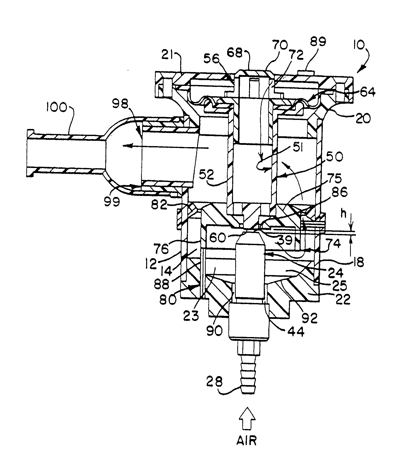
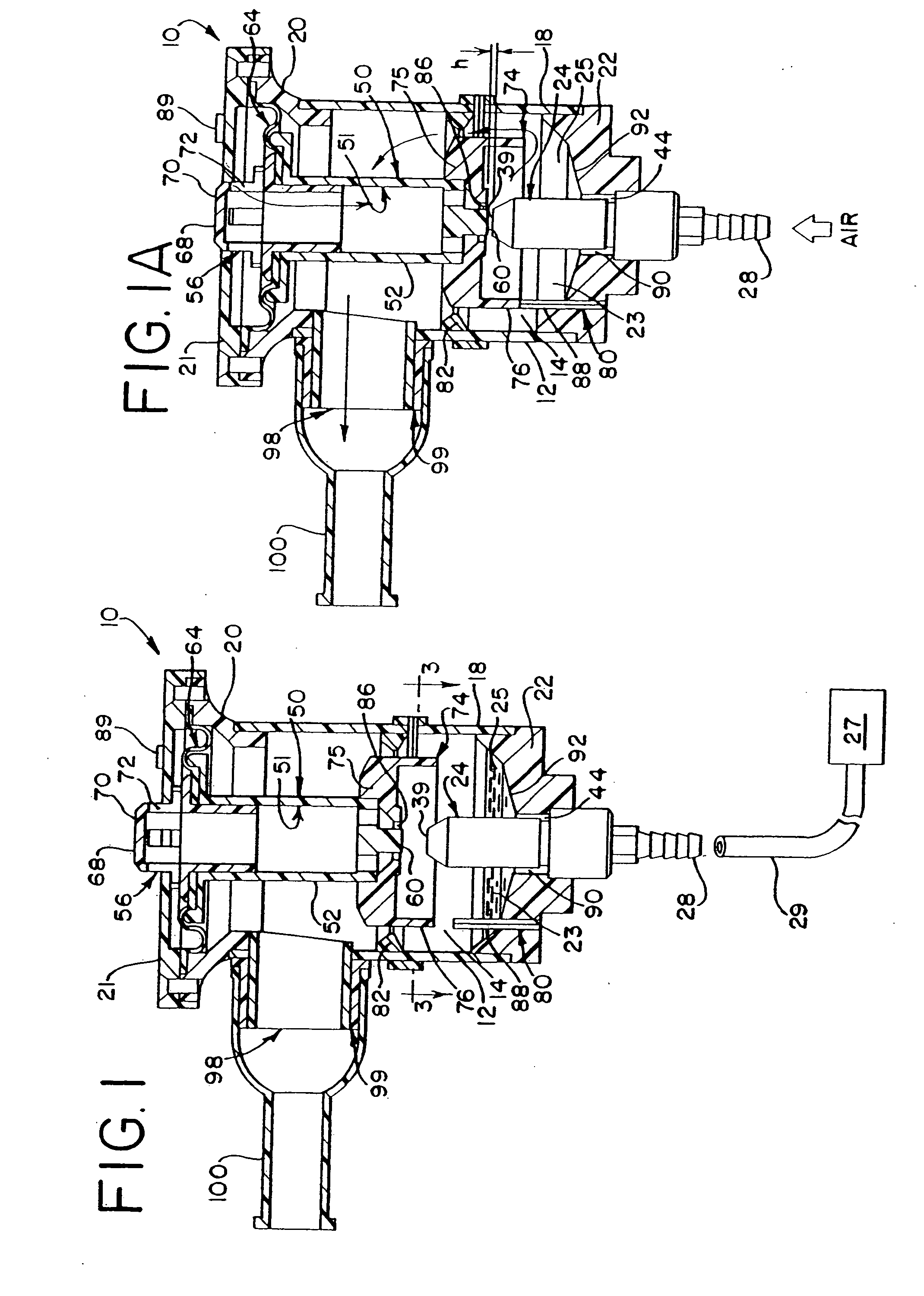
[0031] A first preferred embodiment of a nebulizer 10 is illustrated in FIG. 1. The nebulizer 10 is a small volume nebulizer and includes a housing or container 12 defining an internal chamber 14. The housing 12 is formed of a cylindrically-shaped side wall portion 18, a top portion 20, and a bottom portion 22. The component parts of the housing 12 may be formed of separate, multiple pieces of material that are connected together by welding, adhesives, etc., or more preferably, some of the component parts may be formed together of a single piece of material formed by an injection molding process. For example, the bottom, and side portions 22 and 18 may be formed of separate pieces that are connected together, or preferably, these parts may be formed of one piece of molded plastic. Any of a number of plastics may be suitable, including polycarbonate, or polycarbonate blends. A cover 21 is removably mounted on the upper portion of the housing 12, such as by means of...

second embodiment

II. Second Embodiment

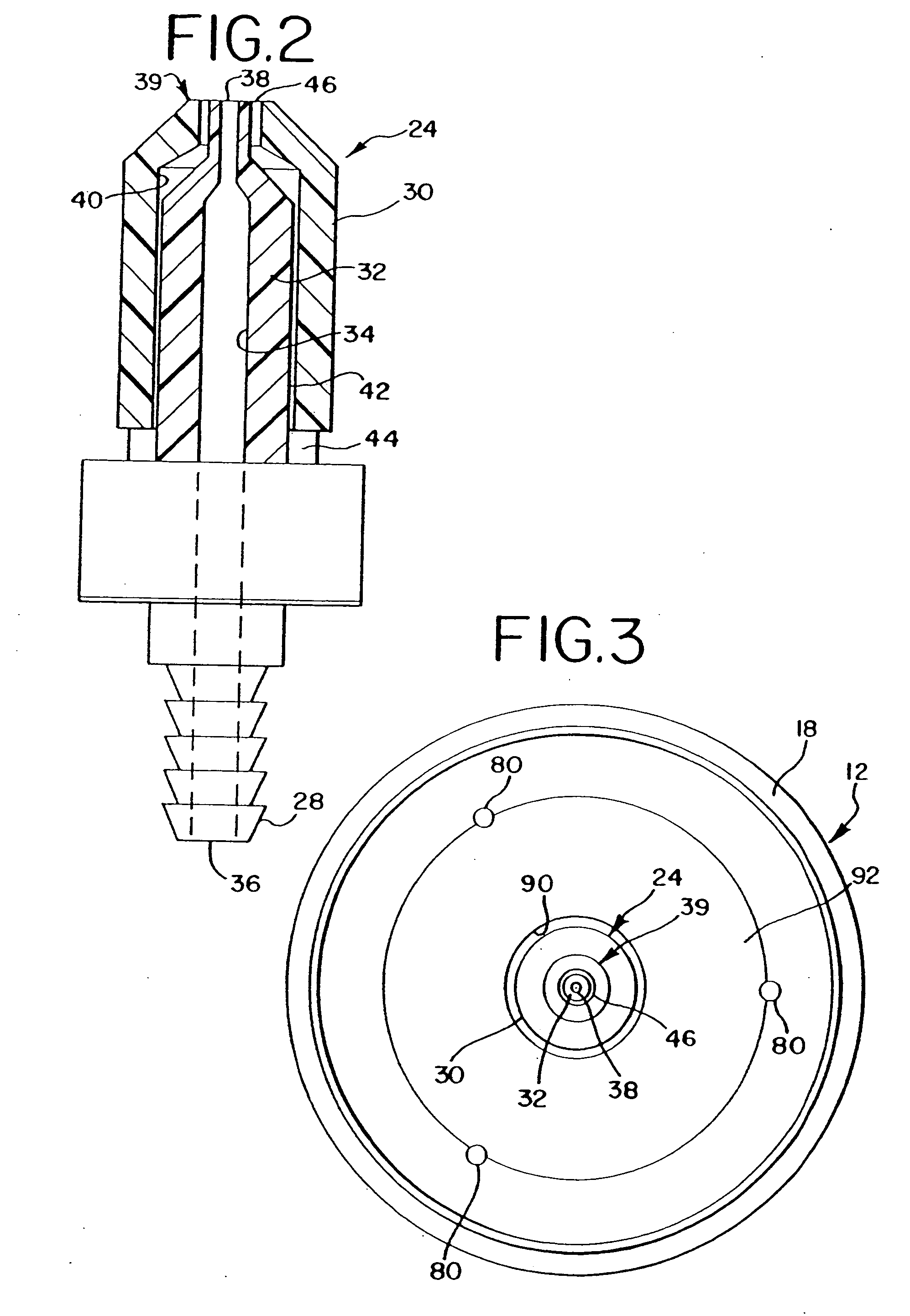
[0075] A second embodiment of a nebulizer is shown in FIG. 5. According to this embodiment, a nebulizer 110 has a housing 112 that defines a chamber 114. A lower portion of the chamber 114 serves as a reservoir 123 for holding a liquid to be nebulized. Located in a lower portion of the housing 112 is a nozzle assembly 124. The nozzle assembly 124 may be similar or identical to the nozzle assembly of the first embodiment, described above. Like the first embodiment, a bottom of the nozzle assembly 124 has a fitting 128 that can be connected to a supply of pressured gas 127 by means of conventional tubing 129. Located in the nozzle assembly 124 are inner and outer tubular members that define gas and liquid passageways that exit at gas and liquid orifices at the top of the nozzle assembly 124, as in the first embodiment. Like the first embodiment, the gas and liquid orifices preferably have a concentric arrangement with the liquid orifice having an annular shape enc...

third embodiment

III. Third Embodiment

[0086] A nebulizer 210 according to another embodiment of the invention is shown in FIGS. 11-13. The nebulizer 210 is similar to the previous embodiments of the nebulizers discussed above. The nebulizer 210 includes a housing 212 defining a chamber 214. In the embodiment of FIG. 11, the housing 212 is relatively larger than the housings of the previous embodiments. For example, the housing 212 may have a height of approximately 11 cm (4.33 in.) and a diameter of approximately 9 cm (3.54 in.). This enables the nebulizer 210 to hold a correspondingly larger volume of liquid and aerosol. A large size nebulizer, such as shown in FIG. 11, may be suitable for certain veterinary applications such as for horses, cattle, dogs, etc. A larger size nebulizer may also be used with humans for uses such as sputum induction.

[0087] A fitting 238 connects to a pressurized gas supply (not shown) and an outlet 298 provides nebulized medicine from the chamber 214 to the patient The...


PUM


Abstract

An apparatus and method for providing a nebula or aerosol to a patient. In one aspect, a nebulizer is pressure sensitive so that nebulization is coordinated with a breathing cycle of the patient. The nebulizer includes a movable gas diverter that diverts pressurized gas across a liquid outlet. The diverter is moved in response to the patient's breathing cycle. In one aspect, a biasing member moves the diverter. According to another aspect of the nebulizer, an annular liquid orifice disperses an aerosol in a radial direction in response to a pressurized gas flow from an orifice located concentrically thereto. Multiple liquid orifices may be provided. In a further aspect of the nebulizer, a reservoir includes an upper, wide portion and a lower narrow portion to apply relatively uniform pressure at a liquid orifice.

Description

BACKGROUND OF THE INVENTION [0001] The present invention relates to a method and apparatus for delivering an aerosol, nebulized liquid or solid medicine or a vapor to a patient's respiratory tract, and more particularly, the present invention relates to an improved nebulizer that provides an aerosol more efficiently and with improved particle size uniformity. [0002] Medical nebulizers for generating a fine spray or nebula of a liquid medicine that can be inhaled by a patient are well known devices commonly used for the treatment of certain conditions and diseases Nebulizers have applications in treatments for conscious, spontaneously-breathing patients and for controlled ventilated patients. [0003] In some nebulizers, a gas and a liquid are mixed together and directed against a baffle. As a result, the liquid is aerosolized, that is, the liquid is caused to form into small particles that are suspended in the air. This aerosol of the liquid can then be inhaled into a patient's respir...

Claims


Application Information

Patent Timeline
Patent Type & Authority Applications(United States)
IPC IPC(8): A61M11/00A61M11/02A61M11/06A61M15/00A61M16/00A61M16/10A61M16/20
CPCA61M11/06A61M15/0091A61M2016/0027A61M2205/3306A61M16/206A61M15/0021A61M15/008A61M15/0093A61M16/107A61M11/002A61M16/0833
Inventor GRYCHOWSKI, JERRY R.BARAN, GEORGEFOLEY, MARTIN P.
Owner TRUDELL MEDICAL INT INC
Why Eureka
Try Eureka