Locking mechanism for movable subframe of tractor-trailers

a technology of locking mechanism and tractor-trailer, which is applied in the direction of tractor-trailer combination, transportation and packaging, vehicles, etc., can solve the problems of lateral or side loads of vehicles containing more than one non-steerable axle, including tractor-trailers, and overload situations

Inactive Publication Date: 2007-02-01
HENDRICKSON USA L L C
View PDF12 Cites 16 Cited by
  • Summary
  • Abstract
  • Description
  • Claims
  • Application Information

AI Technical Summary

Benefits of technology

[0016] An objective of the present invention is to provide a slider box incorporating an improved locking mechanism that securely fastens a slider tandem to the trailer body rails of a tractor-trailer.
[0017] Another objective of the present invention is to provide a slider box incorporating an improved locking mechanism that allows the operator to easily lock and unlock the slider tandem for easy repositioning of the slider tandem with respect to the trailer body rails, while effectively substantially minimizing the stresses associated with the relatively loose fit of prior art locking pin mechanisms.
[0018] Yet another objective of the present invention is to provide a slider box incorporating an improved locking mechanism that allows for the use of lighter materials, such as aluminum, in constructing the trailer body rails, cross sills, and other components of the slider box, and which in turn significantly reduces the overall weight of the trailer, thereby improving cargo-carrying efficiency.
[0019] A further objective of the present invention is to provide a slider box incorporating an improved locking mechanism that reduces the amount of effort expended by the operator when repositioning the slider tandem, and further permits the operator to easily determine whether the slider box is properly engaged, thereby improving safety for the operator and the traveling public.

Problems solved by technology

However, the leaf spring suspension system was unable to provide adequate load equalization between the axles of the slider tandem and therefore was subject to possible overload situations.
Unfortunately, prior art slider boxes equipped with air suspensions add unwanted weight to the trailer, primarily because those slider boxes were originally built to support leaf spring suspensions and adapting them to incorporate air suspensions required additional bracing and support.
Additionally, vehicles containing more than one non-steerable axle, including tractor-trailers, are subject to lateral or side loads.
Moreover, a slider box is subjected to strong vertical and longitudinal or fore-aft loads.
This increases the weight of the frame, thereby reducing the amount of payload that can be carried by the tractor-trailer as governmental weight limitations remain constant irrespective of the weight of the vehicle.
Slider boxes made of steel have contributed to the excessive weight problems that have plagued slider tandems in the past.
However, attempts to utilize materials that are lighter than steel to construct slider boxes, such as aluminum, have been largely unsuccessful and inefficient.
However, these pins can become jammed.
More specifically, slight movement of the slider tandem relative to the trailer body during operation of the tractor-trailer can cause slight misalignment between the respective slider box and trailer body openings through which each pin extends or passes when in the locked position.
Thus, when prior art pins become jammed, the operator of the tractor-trailer risks personal injury due to overexertion in attempting to manually free jammed pins, and further risks damaging the retractable pin mechanism.
However, such quick release devices add expense to the slider box, and such an exercise can be time-consuming and also can create wear on the retractable pin mechanism.
Yet another problem associated with prior art locking pins, which is related to the pin jamming problem, is that the holes formed in the trailer body rails and through which the slider box pins protrude when in the locked position, are approximately 0.25″ oversized to allow the pins to pass through the respective holes after tolerances and deflections are accounted for.
Such movements, in turn, can cause each pin to forcibly contact, or bang, the trailer body rail opening at the interface of the slider pin and the trailer body rail.
Such movement and pin banging, in turn, causes lateral movement and misalignment of the slider tandem, which can adversely affect tracking, cause excessive tire wear, and exacerbate the jamming of pins.
The steel body rails alone add approximately 100 lbs. apiece to the weight of the trailer and further dictate the use of steel cross sills in trailers having a floor structure frame, which enables easy welding of the steel rails to the steel floor structure but also adds additional undesirable weight.

Method used


Image

  • Locking mechanism for movable subframe of tractor-trailers
  • Locking mechanism for movable subframe of tractor-trailers
  • Locking mechanism for movable subframe of tractor-trailers

Examples


Embodiment Construction

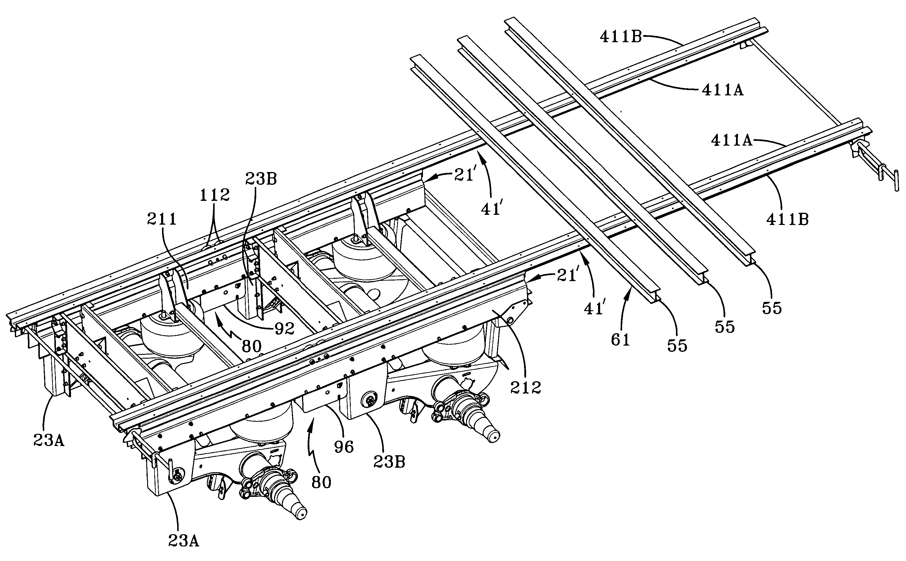
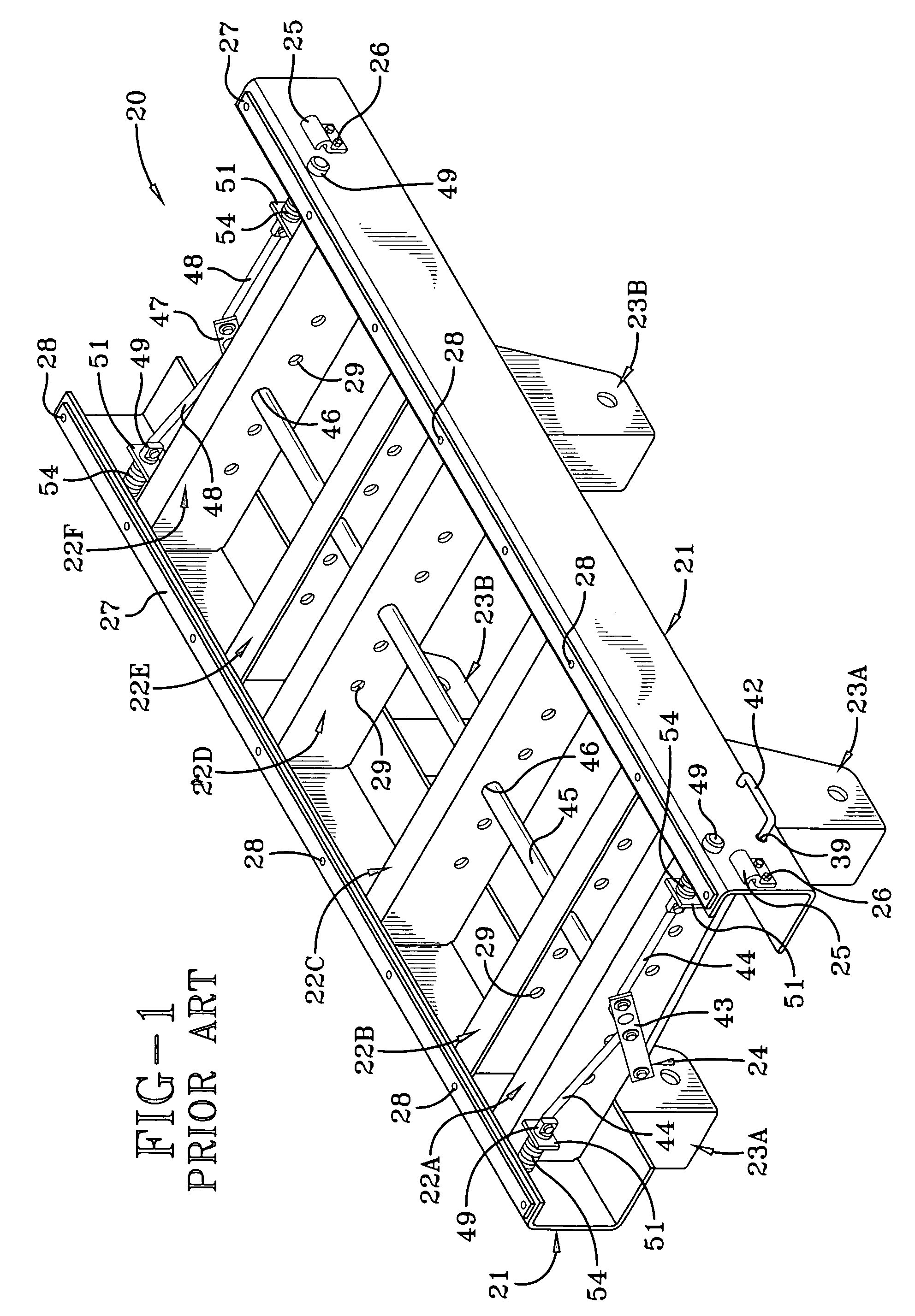
[0036] So that the structure, operation and advantages of the improved locking mechanism for a slider box of the present invention can be best understood, a slider box for a tractor-trailer having a prior art retractable locking pin mechanism is indicated generally at 20 and is shown in FIG. 1. Slider box 20 includes a pair of longitudinally extending main members 21, a plurality of cross members 22A through F, and a retractable pin mechanism 24. Front and rear pairs of hangers 23A and 23B, respectively, are attached to and depend from slider box main members 21 for suspending axle / suspension systems.

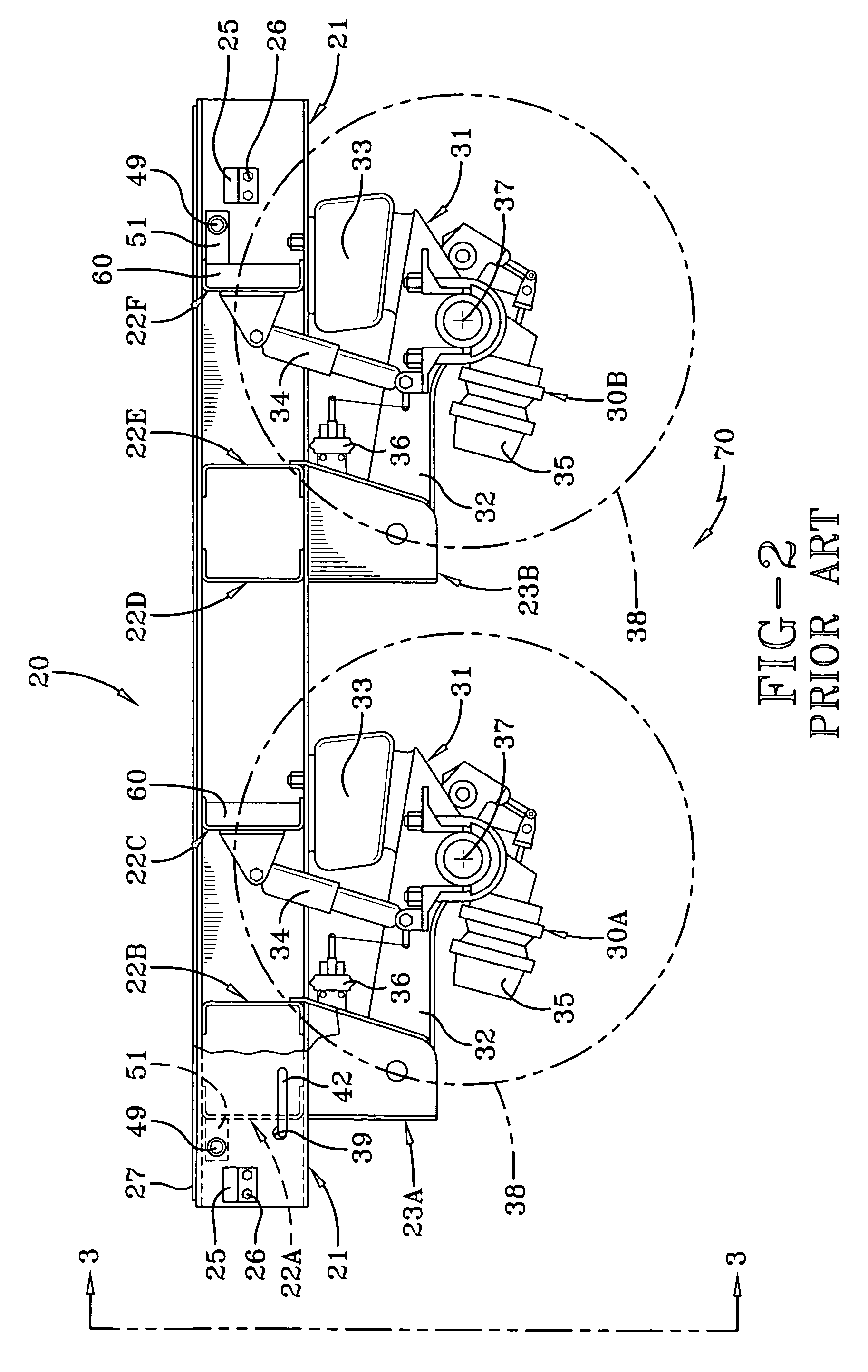
[0037] Specifically, and as further shown in FIG. 2, each main member 21 is an elongated, generally C-shaped beam made of a metal such as steel or other suitable material. The open portion of each main member 21 is opposed to the open portion of the other main member and faces inboard relative to slider box 20. Main members 21 are connected to each other in spaced-apart parallel relati...


PUM


Abstract

An improved locking mechanism for a movable subframe of a tractor-trailer has a pair of transversely-spaced main members extending longitudinally beneath a body of the tractor-trailer, at least one cross member extending between and being attached to the main members, and an axle / suspension system attached to and depending from the main members. At least one clamping mechanism is attached to the subframe and mechanically engages a longitudinally extending rail of the body of the tractor-trailer to enable efficient selective positioning of the subframe relative to the body. Undesirable movements between the subframe and the tractor-trailer body are minimized by fore-aft and / or vertical clamping loads exerted on the body rail and the subframe by the clamping mechanism. This secure positioning allows portions of the trailer body and / or subframe to be constructed of lightweight materials which in turn permits the tractor-trailer to carry larger payloads.

Description

CROSS-REFERENCE TO RELATED APPLICATION [0001] This application claims the benefit of U.S. Provisional Patent Application Ser. No. 60 / 703,910, filed on Jul. 29, 2005.BACKGROUND OF THE INVENTION [0002] 1. Technical Field [0003] The invention relates to tractor-trailer subframes and, in particular, to movable subframes for tractor-trailers. More particularly, the invention is directed to a movable subframe for tractor-trailers which includes a clamping arm mechanism for locking the movable subframe into a selected position relative to the tractor-trailer body, wherein the movable subframe is effectively clamped to the trailer body rails so that gyrations of the subframe are reduced or minimized after the subframe is locked into position and during operation of the vehicle, thereby enabling the use of weight-saving aluminum trailer body rails and cross sills and enhancing the advantages of an aluminum slider box. [0004] 2. Background Art [0005] Specifically, movable subframes, typically...

Claims


Application Information

Patent Timeline
Patent Type & Authority Applications(United States)
IPC IPC(8): B62D53/06
CPCB62D53/068
Inventor RAMSEY, JOHN EDWARD
Owner HENDRICKSON USA L L C
Why Eureka
Try Eureka