Method and apparatus for communication using pulse-width-modulated visible light

a technology of visible light and communication method, applied in the direction of transmission, close-range type system, free-space transmission, etc., can solve the problem of additional power consumption

Active Publication Date: 2007-02-01
AVAGO TECH INT SALES PTE LTD
View PDF9 Cites 162 Cited by
  • Summary
  • Abstract
  • Description
  • Claims
  • Application Information

AI Technical Summary

Problems solved by technology

However, this is cumbersome and consumes additional power, which is often limited in a portable electronic device such as a notebook or laptop computer.

Method used


Image

  • Method and apparatus for communication using pulse-width-modulated visible light
  • Method and apparatus for communication using pulse-width-modulated visible light
  • Method and apparatus for communication using pulse-width-modulated visible light

Examples


Embodiment Construction

[0013] LED backlights provide an alternative to CCFLs for use in display panels. LED backlights can provide a wider range of colors and freedom for the user to change or select the type white point of the backlight. LEDs in a display backlight are controlled to provide the desired color balance and brightness of the display.

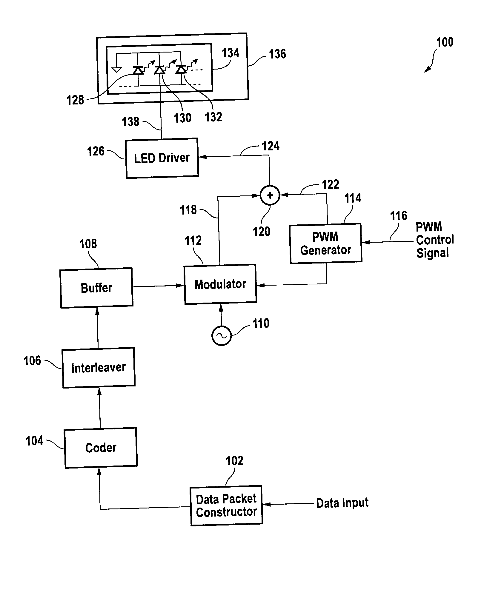
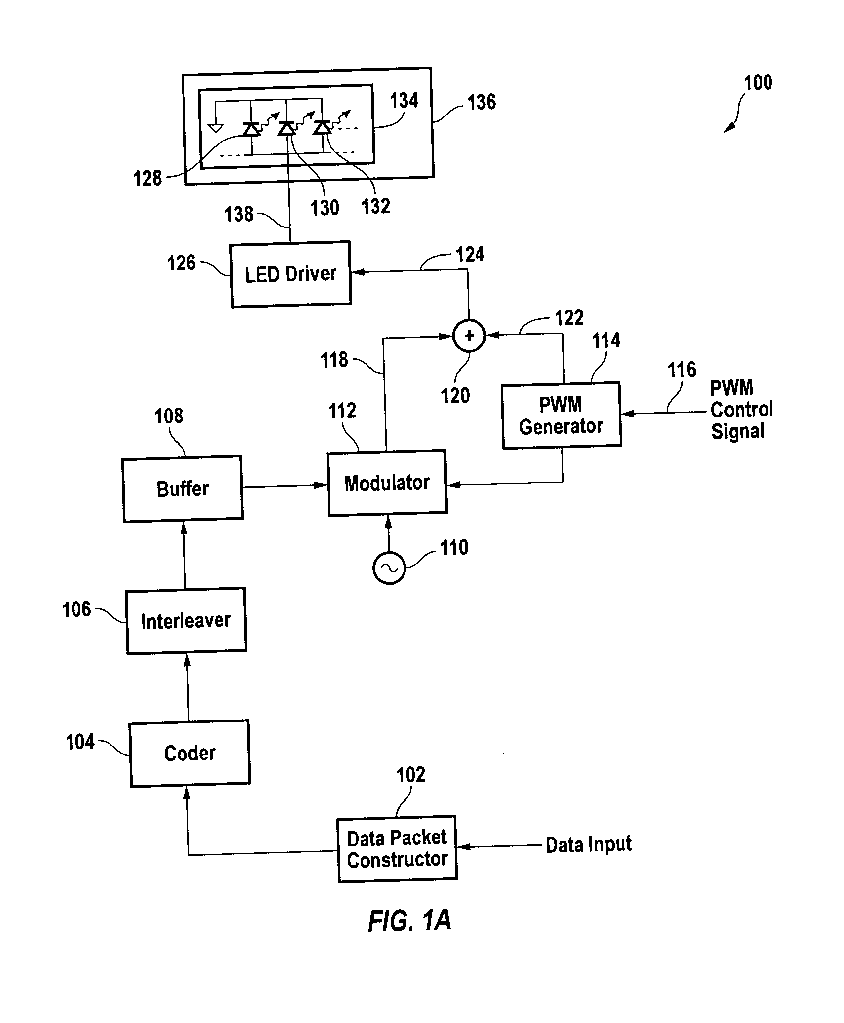
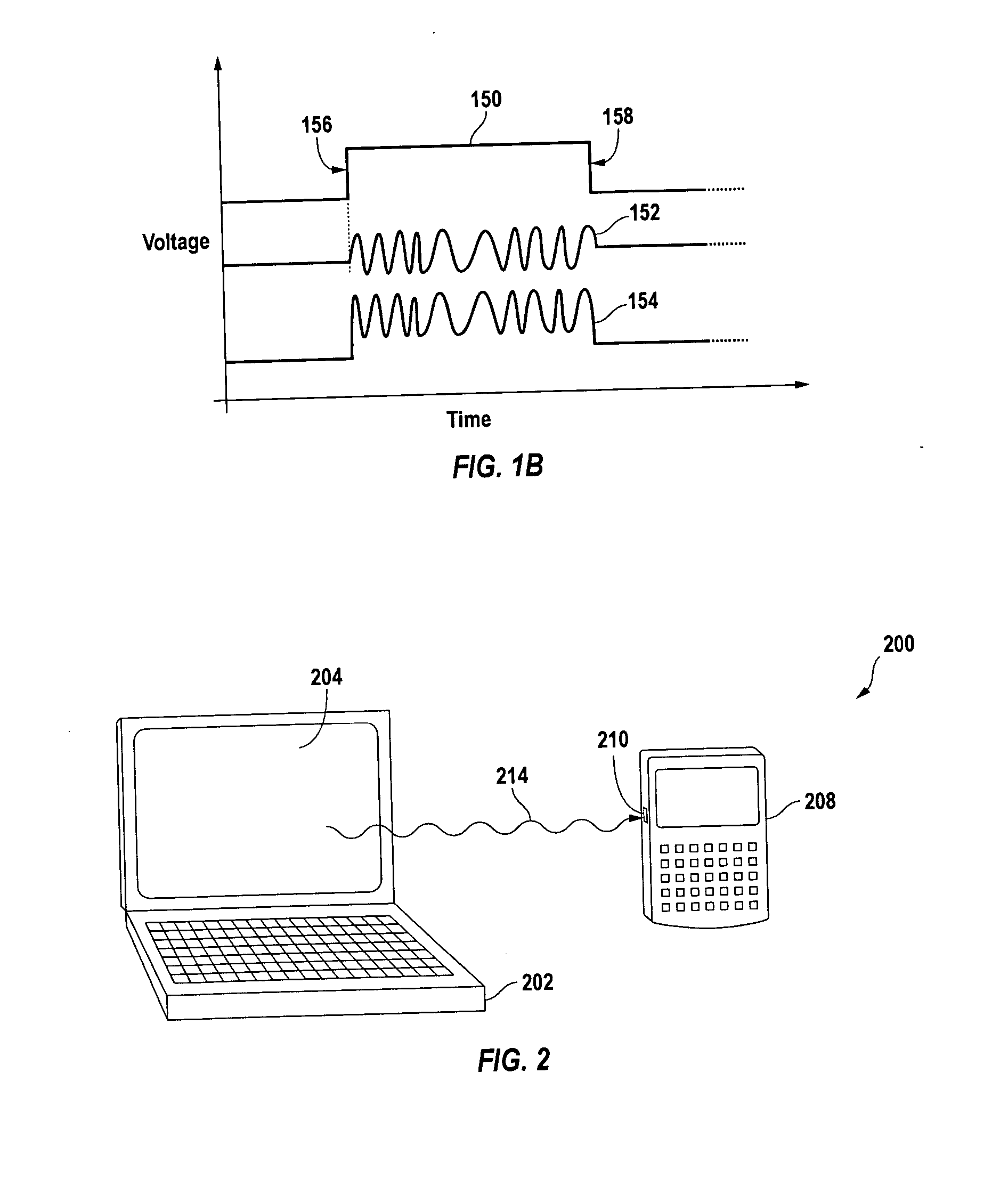
[0014] The chief method of controlling the brightness of LED light sources, such as LED backlights, is by pulse width modulation (“PWM”). Basically, the LEDs in the light source are rapidly turned on and off. The human eye averages the bright ON state and dark OFF state of the light source to perceive a display having essentially constant brightness. Pulses are generated by a PWM generator that drives the LED light source. The length of time that the LED light source is turned ON is controlled by the width of the pulse(s). If the user wants a brighter display, an adjustment (user input) instructs the PWM generator to produce pulses of longer duration.

[0015] How...


PUM


Abstract

A visible light communications transmitter combines a modulated carrier signal with a pulse from a pulse generator. The carrier signal is modulated according to data read from a buffer during the pulse.

Description

CROSS-REFERENCE TO RELATED APPLICATIONS [0001] Not applicable. STATEMENT REGARDING FEDERALLY SPONSORED RESEARCH OR DEVELOPMENT [0002] Not applicable. REFERENCE TO MICROFICHE APPENDIX [0003] Not applicable. BACKGROUND OF THE INVENTION [0004] Display panels, such as those used in personal computers, digital assistants, and mobile (“cell”) telephones, often use a backlight in combination with a diffuser panel to illuminate a liquid-crystal display (“LCD”) panel. The backlight provides white light that is controlled by the LCD panel to produce a color display. Cold-cathode fluorescent lamps (“CCFLs”) are frequently as backlights in display panels. [0005] A CCFL is typically a tube filled with gas or vapor and coated on the inside with phosphors. A current is passed through the tube, causing the gas or vapor to emit light that is converted to other wavelengths by the phosphors to produce white light. The CCFL is typically driven by a sinusoidal signal, and the brightness is regulated by ...

Claims


Application Information

Patent Timeline
Patent Type & Authority Applications(United States)
IPC IPC(8): G09G3/36H04B10/118
CPCH04B10/116H04B10/1141
Inventor MANIAM, SELVANYAP, EIT THIANKEH, KEAN LOO
Owner AVAGO TECH INT SALES PTE LTD
Why Eureka
Try Eureka