
Method of improved controlling of an ink jet printer, and ink jet printer

a technology of ink jet printer and ink jet printer, which is applied in the direction of printing, other printing apparatus, etc., can solve the problems of poor ink level sensor accuracy, affecting the accuracy of ink level sensor, and the situation is far from optimal, so as to achieve the effect of relatively easy optimization

Inactive Publication Date: 2007-02-01
OCE TECH
View PDF0 Cites 30 Cited by
  • Summary
  • Abstract
  • Description
  • Claims
  • Application Information

AI Technical Summary

Benefits of technology

[0010] By considering the printhead as such as a system to which a balance of ink is applied, the amount of ink to be dosed for one or more planned printed tasks can be calculated relatively timely and accurately with respect to dosing of ink based upon information gathered by a conventional ink level sensor. This relatively accurate controlling of the amount of ink, preferably though not exclusively formed by ink pellets (or ink pills), to be dosed during operation of the ink jet printer will lead to a significantly improved control of the ink jet printer, and in particular of the jetting process of the printer.
[0014] In a preferred embodiment, the method for improved controlling of an ink jet printer further comprises step E) of measuring the number of pressure pulses, in particular activation pulses, to selectively expel the ink droplets via the nozzle, wherein according to step C) the amount of a ink contained by the printhead is based upon measured values gathered in steps A), B) and E). By measuring the number of pressure pulses, in particular activation pulses, an indication can be obtained of the number of ink droplets released by the nozzle(s), which commonly extends, and hence improves the balance of matter, in particular the balance of ink, of the ink jet printer. Waste-ink created by purging and cleaning the ink reservoir can be compensated for in the method according to the invention, for example by resetting reference values before actually monitoring the printing process, and in particular the jetting process.
[0016] Inter alia, to be able to calibrate the measured values gathered with the method according to the present invention, the method for improved controlling of an ink jet printer preferably further comprises step F) of measuring an ink level within at least one ink reservoir of the printhead. Calibration of the printhead to which the method is applied can be performed on a long term time scale by measuring the ink level within the ink reservoir. To optimize the reliability of reference values to be obtained by the (hardware) ink level sensor for calibration of the printhead, preferably measurements by the ink level sensor are taken which are performed under relatively stable conditions, wherein the uncertainty in the ink level sensor is relatively small. To this end, reference values may be obtained, e.g. by not moving a carriage carrying the printhead for more than approximately 30 seconds since the last ink pill was dosed with the carriage positioned at a well-defined position under well-defined thermal conditions. The ink level within the ink reservoir can be detected by means of different kinds of sensors such as a float level indicator, electrical resistance, and a thermal sensor. Though preferably during step F) the ink level within the ink reservoir is measured by means of at least one thermistor, more preferably an NTC thermistor. Application of an NTC thermistor is relatively inexpensive with respect to the application of other types of thermal sensors. However, under specific circumstances it could also be conceivable for a person skilled in the art to apply a PTC type thermistor, or even other kinds of temperature sensitive (electronic) detecting means.
[0018] As aforementioned, the ink dosed to the printhead is preferably formed by hot melt pellets. To melt these ink pellets and to keep these pellets in a molten state within the ink reservoir(s) of the printhead, the ink within the ink reservoir(s) is preferably heated. In this manner, the ink contained within the ink reservoir(s) can be kept easily at an elevated temperature typically of about 130° Celsius.
[0022] As aforementioned, the total amount of ink contained by the printhead can be determined by making up a balance of matter, in particular a balance of ink, as a result of which the process for dosing ink (pellets) to the printhead can be optimized relatively easily though accurately. To be able to calibrate these mechanisms from time to time, it is advantageous that the ink jet printer further comprises a detector, in particular one or more ink level sensors, that detect the ink level within each ink reservoir. To be able to make a realistic assessment of the release of ink by the printhead, the second counting mechanism is preferably adapted to count the number of pressure pulses, in particular activation pulses, produced to expel the ink droplets via the nozzles.

Problems solved by technology

This situation is far from optimal due to a lack of accuracy of the ink level sensor.
Specifically, the sensor is merely adapted to perform a small range detection, only a certain (and single) threshold level can be detected when exceeded, and accurate detection of the ink level sensor is hindered due to thermal inertia of the sensor.
Besides a relatively poor accuracy of the ink level sensor, the known method of determining the amount of ink to be dosed is not optimal, since the level in the ink reservoir is not the same as the total amount of ink within the printhead.

Method used


Image

  • Method of improved controlling of an ink jet printer, and ink jet printer
  • Method of improved controlling of an ink jet printer, and ink jet printer

Examples


Embodiment Construction

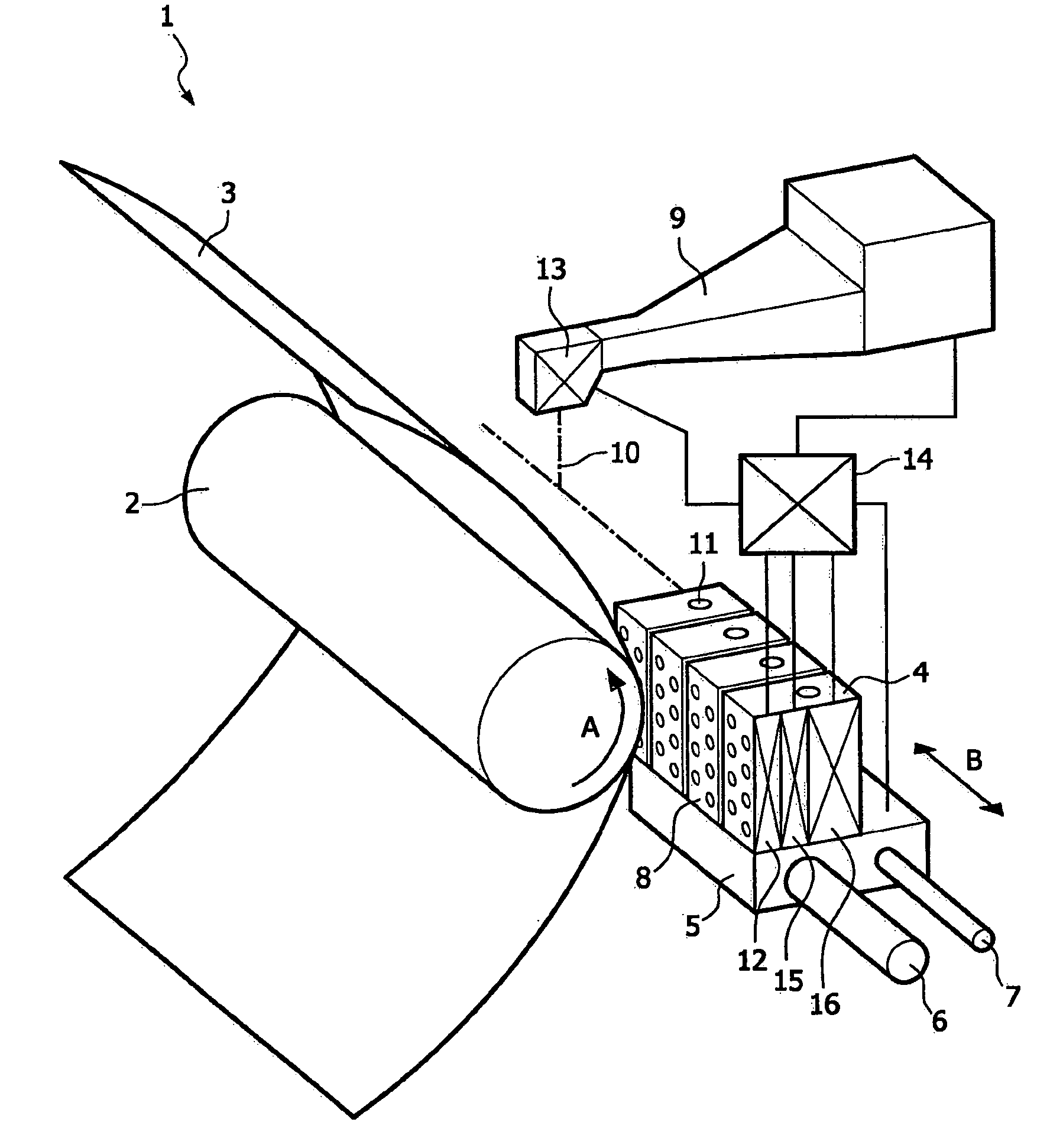
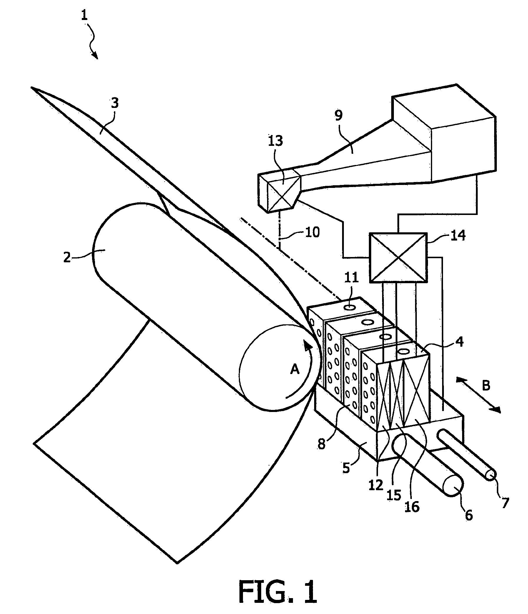
[0026]FIG. 1 is a perspective view of an ink jet printer 1 according to an embodiment of the present invention. In this embodiment the printer 1 includes a roller 2 to support a substrate 3 and move it along the four printheads 4. The roller 2 is rotatable about its axis as indicated by arrow A. A carriage 5 carries the four printheads 4 and can be reciprocated in the direction indicated by the double arrow B, parallel to roller 2. In this way, the printheads 4 can scan the receiving substrate 3, for example a sheet of paper. The carriage 5 is guided over rods 6 and 7 and is driven by means suitable for the purpose (not shown). In the embodiment shown in this figure, each printhead 4 contains eight ink reservoirs (not shown) connected to eight ink ducts, each with its own nozzle 8, which form two rows of four nozzles 8 each perpendicular to the axis of the roller 2. In a practical embodiment of the printer 1, the number of ink ducts per printhead 4 and the number of nozzles per prin...


PUM


Abstract

A method for improved controlling of an ink jet printer includes measuring the amount of ink dosed to at least one printhead of the ink jet printer, measuring the amount of ink droplets released by at least one nozzle of the printhead, and determining the amount of a ink contained by the printhead by using the amounts measured. A computer program and a computer running the computer program are adapted to carry out the method. Moreover, an ink jet printer is adapted to perform the method.

Description

CROSS-REFERENCE TO RELATED APPLICATIONS [0001] This nonprovisional application claims priority under 35 U.S.C. § 119(a) on Patent Application No. 05106849.2, filed in Europe on Jul. 26, 2005, the entirety of which is incorporated herein by reference. BACKGROUND OF THE INVENTION [0002] 1. Field of the Invention [0003] The present invention relates to a method for improved controlling of an ink jet printer. The present invention also relates to a computer program adapted for carrying out the method according to the invention. The present invention further relates to a computer running the computer program according to the invention. Moreover, the present invention relates to an ink jet printer adapted to perform the method according to the invention. [0004] 2. Description of Background Art [0005] It is known in the background art to apply an ink level sensor for an ink jet printer within an ink reservoir of a printhead to detect the ink level when it exceeds a certain threshold level....

Claims


Application Information

Patent Timeline
Patent Type & Authority Applications(United States)
IPC IPC(8): B41J29/38
CPCB41J2/17509B41J2/17593B41J2/17566
Inventor REINTEN, HANSTHEUWS, PETER G.F.
Owner OCE TECH
Learn More