Protection apparatus

a technology of protection apparatus and protective shield, which is applied in the direction of emergency protection devices, electrical devices, emergency protection circuit arrangements, etc., can solve the problems that the arc discharge generated at the time of blowing the thermal fuse may continue to induce disadvantage, and achieve the effect of preventing overheating and increasing the adaptive rang

Inactive Publication Date: 2007-02-01
HONDA MOTOR CO LTD +1
View PDF7 Cites 9 Cited by
  • Summary
  • Abstract
  • Description
  • Claims
  • Application Information

AI Technical Summary

Benefits of technology

[0014] An advantage of the present invention is that an economic protection apparatus can be provided using general-purpose products commercially available for the thermal fuse and electrosensitive fuse. By connecting an electrosensitive fuse in parallel with a thermal fuse, usage is allowed in an area exceeding the rated voltage and current of a thermal fuse. Further, arc discharge that occurs immediately after cut-off of the thermal fuse can be prevented. Particularly in the area of use of a thermal fuse employed for a power supply or load directed to a high voltage and high current load to prevent overheating, the applicable region to a high load apparatus can be extended by virtue of the parallel connection with an electrosensitive fuse. The disadvantage occurring at the time of overheating can be prevented. The production apparatus of the present invention allows the provision of safety protection means for car air conditioners and motor-driven tools in relation to vehicle-mounted systems and DC motors. Since the applicable range of the thermal fuse can accommodate load with the breaking current of 35 A-10000 A and voltage of AC600V or DC600V, the adaptive range can be increased.
[0015] The foregoing and other objects, features, aspects and advantages of the present invention will become more apparent from the following detailed description of the present invention when taken in conjunction with the accompanying drawings.

Problems solved by technology

When this thermal fuse is used with a DC (Direct Current) power supply, the arc discharge that is generated at the time of blowing the thermal fuse may continue to induce disadvantage.
In other words, when the thermal fuse senses overheating and is activated at the operating temperature to interrupt the circuit, the plasma generated between the contacts that are cut off by the thermal fuse may continue to cause plasma discharge since the polarity does not change as an alternate current, thus leading to contingencies.

Method used


Image

  • Protection apparatus
  • Protection apparatus

Examples


Embodiment Construction

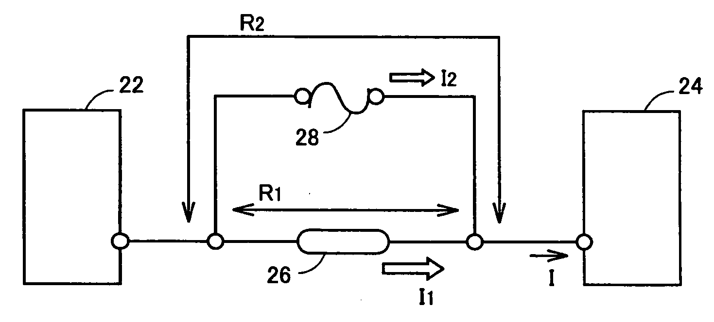
[0019] A protection apparatus employing a thermal fuse of the present invention includes a protection circuit. The protection circuit includes a thermal fuse with a predetermined operating temperature, activated in response to sensing overheating at a power supply and / or a load, and an electrosensitive fuse, connected in parallel with the thermal fuse, and activated at a predetermined operating current. The protection circuit is connected in series with the power supply and load. The electrosensitive fuse is characterized in that it is activated only after the thermal fuse has been activated at a predetermined operating temperature. Since the protection apparatus can be used at a load directed to high voltage and high current, the area of use of the thermal fuse can be extended.

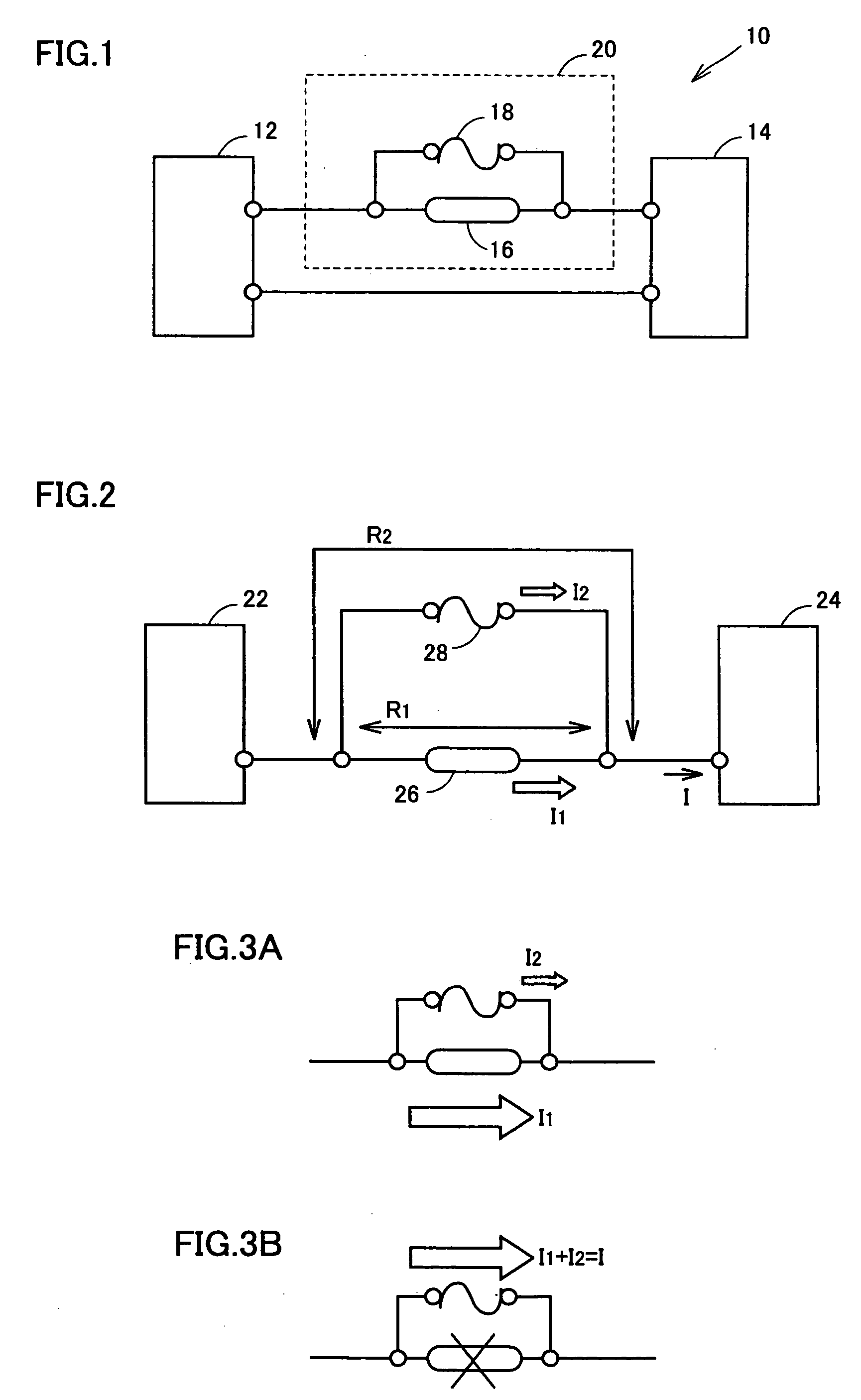
[0020]FIG. 1 is a circuit diagram of a protection apparatus employing a thermal fuse of the present invention. A protection apparatus 10 of the present invention has a direct current power supply 12 and a lo...


PUM


Abstract

A protection apparatus is provided that can use a thermal fuse at higher voltage and higher current. The protection apparatus includes a protection circuit connected in series between a power supply and a load. The protection circuit includes a thermal fuse with a predetermined operating temperature, activated in response to sensing overheating of the power supply and/or load, and an electrosensitive fuse connected in parallel with the thermal fuse, and activated at a predetermined operating current. The electrosensitive fuse is adapted to be activated only after the thermal fuse has been activated at the predetermined operating temperature.

Description

BACKGROUND OF THE INVENTION [0001] 1. Field of the Invention [0002] The present invention relates to a protection apparatus employing a thermal fuse, including a protection circuit to extend the area of use of the thermal fuse to equipment directed to high voltage and high current. Particularly, the present invention relates to a protection apparatus that can avoid an abnormal event immediately after activation of a thermal fuse by using an electrosensitive fuse with the thermal fuse. [0003] 2. Description of the Background Art [0004] A thermal fuse is a protection component to properly sense abnormal overheating at the electric apparatus and quickly cut off the circuit. A thermal fuse is employed in various home electrical products, portable apparatuses, communication equipment, business machines, in-car devices, air conditioners, AC adapters, chargers, batteries, and electronic components. In general, thermal fuses are mainly classified into two types depending upon the thermosens...

Claims


Application Information

Patent Timeline
Patent Type & Authority Applications(United States)
IPC IPC(8): H02H5/04
CPCH01H37/761H01H85/048H01H85/0241H01H37/764H02H5/04
Inventor NISHIKAWA, MASAHIRO
Owner HONDA MOTOR CO LTD
Why Eureka
Try Eureka