
Optimal bridging over MPLS / IP through alignment of multicast and unicast paths

a multicast and unicast path technology, applied in the field of digital computer network technology, can solve the problems of inability to meet high bandwidth applications, inability to completely eliminate the replication problem at the ingress pe, and inefficient replication mpls/ip core network resources of the ingress p

Active Publication Date: 2007-02-01
CISCO TECH INC
View PDF76 Cites 79 Cited by
  • Summary
  • Abstract
  • Description
  • Claims
  • Application Information

AI Technical Summary

Problems solved by technology

This ingress replication is very inefficient in terms of ingress PE and MPLS / IP core network resources.
Furthermore, it is not viable for high bandwidth applications where replicating the multicast data N times may exceed the throughput of the ingress PE trunk.
Although IGMP snooping helps to alleviate replication overhead, it does not completely eliminate the replication problem at the ingress PE.
Therefore, this mechanism may not be viable for multicast applications with high bandwidth requirements because the aggregate data throughput after replication may exceed the bandwidth of the physical trunk at the ingress PE.
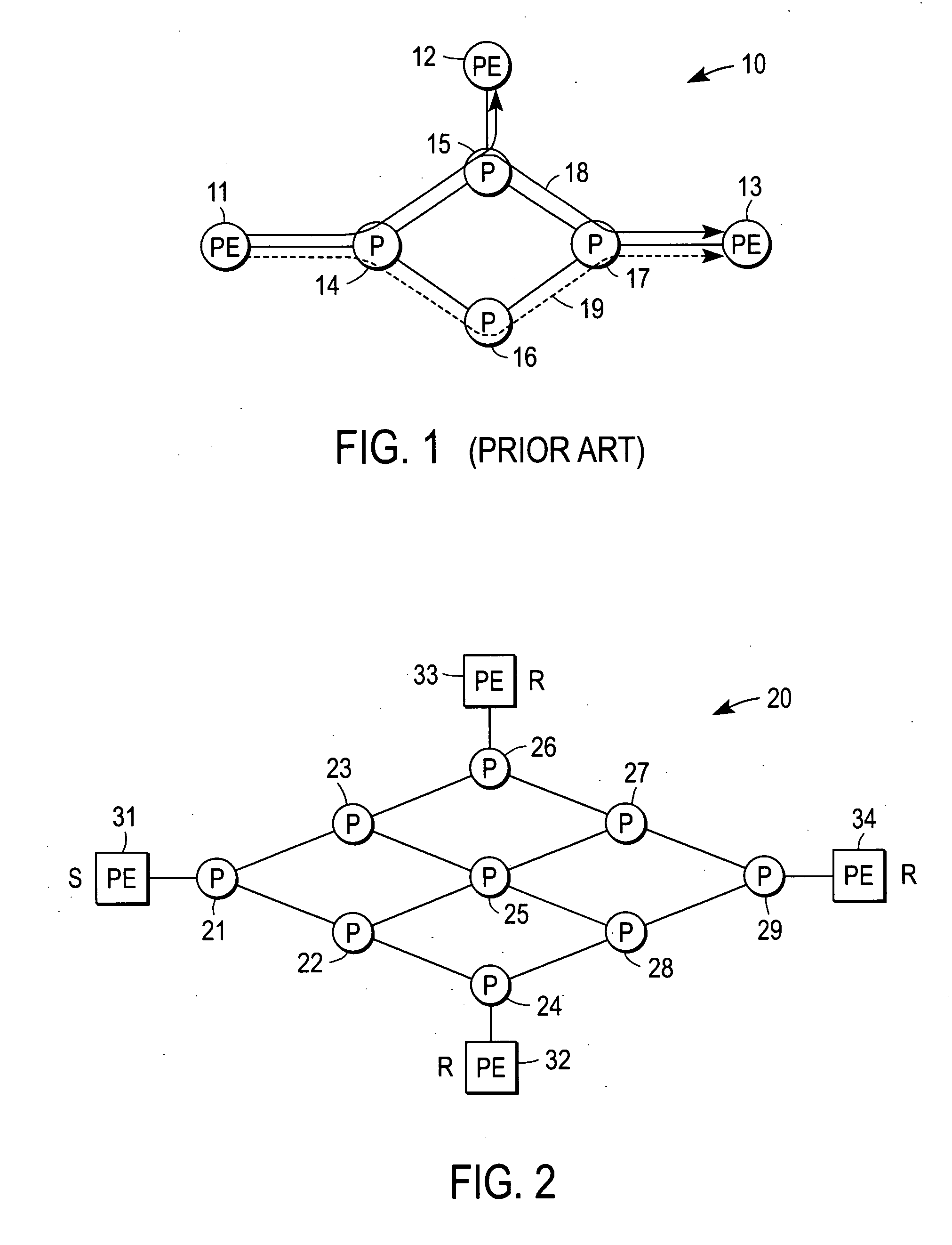
However, because the unicast and multicast paths for a given VPLS instance are different, this approach can result in numerous problems.
The first problem involves packet re-ordering, wherein two consecutive frames are sent on two different paths, e.g., a first frame is sent on a multicast path because of unknown destination unicast MAC address, with a second frame being sent on a unicast path after the path to the destination has been learned.
Another problem with the second IETF proposal is that bridged control packets typically need to take the same path as unicast and multicast data, which means the unicast and multicast path need to be aligned or congruent.
Furthermore, since unicast and multicast paths are usually different in the network core, Ethernet operations, administration, and management (OAM) connectivity check messages often cannot detect a path / node failure.
Even if the failure is detected through some other means, notification of the failure to the originator of the Ethernet OAM becomes problematic.

Method used


Image

  • Optimal bridging over MPLS / IP through alignment of multicast and unicast paths
  • Optimal bridging over MPLS / IP through alignment of multicast and unicast paths
  • Optimal bridging over MPLS / IP through alignment of multicast and unicast paths

Examples


Embodiment Construction

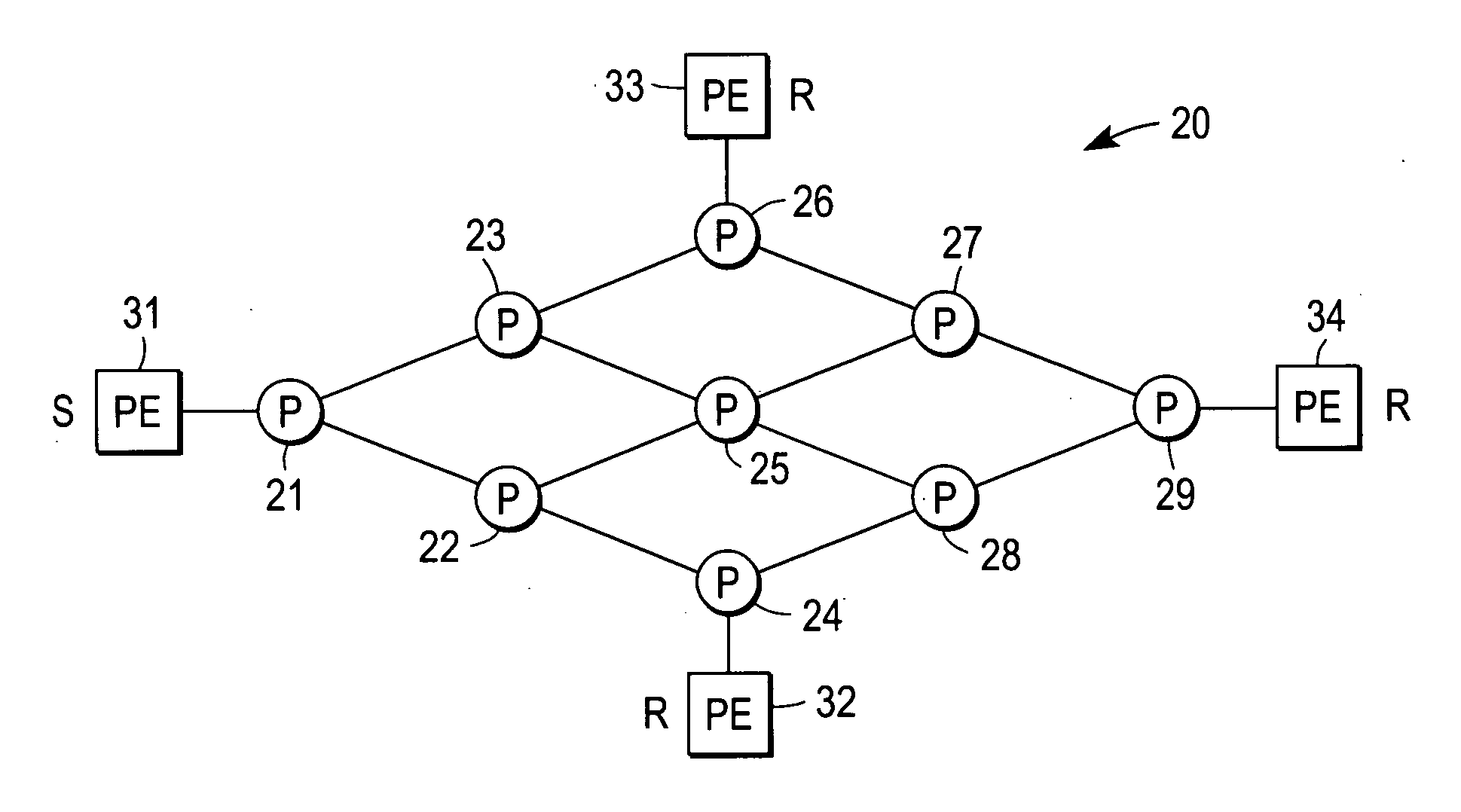
[0022] A mechanism for aligning unicast and multicast paths in a service provider network, and which thereby achieves shortest path (i.e., optimal) bridging, is described. In the following description specific details are set forth, such as device types, protocols, network configurations, etc., in order to provide a thorough understanding of the present invention. However, persons having ordinary skill in the networking arts will appreciate that these specific details may not be needed to practice the present invention.

[0023] A computer network is a geographically distributed collection of interconnected subnetworks for transporting data between nodes, such as intermediate nodes and end nodes. A local area network (LAN) is an example of such a subnetwork; a plurality of LANs may be further interconnected by an intermediate network node, such as a router, bridge, or switch, to extend the effective “size” of the computer network and increase the number of communicating nodes. Example...


PUM


Abstract

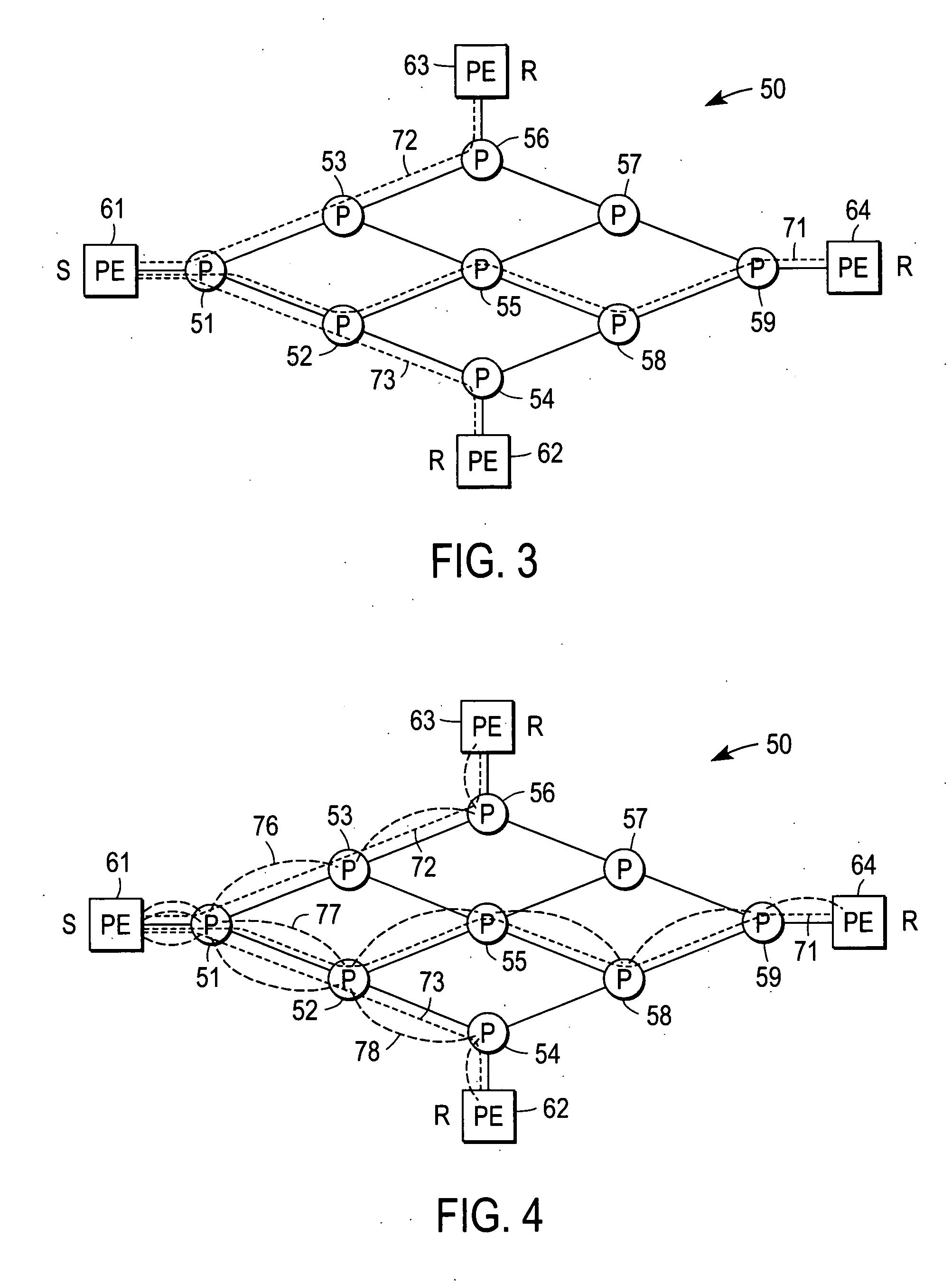
A provider edge (PE) node of a network operates to send a trace path message over the network to a receiver PE node, the trace path message recording a list of intermediate nodes of a unicast path from the PE node to the receiver PE node; and receive a join message initiated from the receiver PE node, the join message using the list to propagate to the source PE node through the intermediate nodes such that a branch of a multicast tree is aligned with the unicast path. It is submitted with the understanding that it will not be used to interpret or limit the scope or meaning of the claims. 37 CFR 1.72(b).

Description

RELATED APPLICATIONS [0001] This application claims the benefit of U.S. Provisional Patent Application No. 60 / 704,817 filed Aug. 1, 2005, entitled “Multicast Mechanism For VPLS”. The present application is also related to co-pending application entitled, “Congruent Forwarding Paths For Unicast and Multicast Traffic” filed concurrently herewith, which application is assigned to the assignee of the present application.FIELD OF THE INVENTION [0002] The present invention relates generally to digital computer network technology; more particularly, to methods and apparatus for providing Local Area Network (LAN) emulation services over Internet protocol (IP) networks. BACKGROUND OF THE INVENTION [0003] A LAN is a high-speed network (typically 10 to 1000 Mbps) that supports many computers connected over a limited distance (e.g., under a few hundred meters). Typically, a LAN spans a single building. U.S. Pat. No. 6,757,286 provides a general description of a LAN segment. A Virtual Local Area...

Claims


Application Information

Patent Timeline
Patent Type & Authority Applications(United States)
IPC IPC(8): H04L12/28
CPCH04L45/26H04L45/00
Inventor SAJASSI, ALIFARINACCI, DINOZWIEBEL, JOHN M.ALVAREZ, DANIEL
Owner CISCO TECH INC
Learn More