Sound source separation apparatus and sound source separation method

a separation apparatus and sound source technology, applied in the field of sound source separation apparatus and sound source separation method, can solve the problems of increasing computing load, affecting the performance affecting the quality of sound source separation, etc., to achieve the effect of maximizing sound source separation performan

Inactive Publication Date: 2007-02-01
KOBE STEEL LTD
View PDF0 Cites 25 Cited by
  • Summary
  • Abstract
  • Description
  • Claims
  • Application Information

AI Technical Summary

Benefits of technology

[0009] The present invention has been made in view of the circumstances described above, and an object thereof is to provide a sound source sepa

Problems solved by technology

However, achieving a sufficient level of sound source separation performance requires an increased number of sequential calculations (learning calculations) for determining a separating matrix to be used for separation (filtering) and thus increases the computing load.
Performing such calculations by a widely used processor takes a long time that is several times the

Method used


Image

  • Sound source separation apparatus and sound source separation method
  • Sound source separation apparatus and sound source separation method
  • Sound source separation apparatus and sound source separation method

Examples


Embodiment Construction

[0033] Embodiments of the present invention will now be described with reference to the accompanying drawings for aid in understanding the present invention. The following embodiments are provided for exemplary purposes and are not intended to limit the technical scope of the present invention.

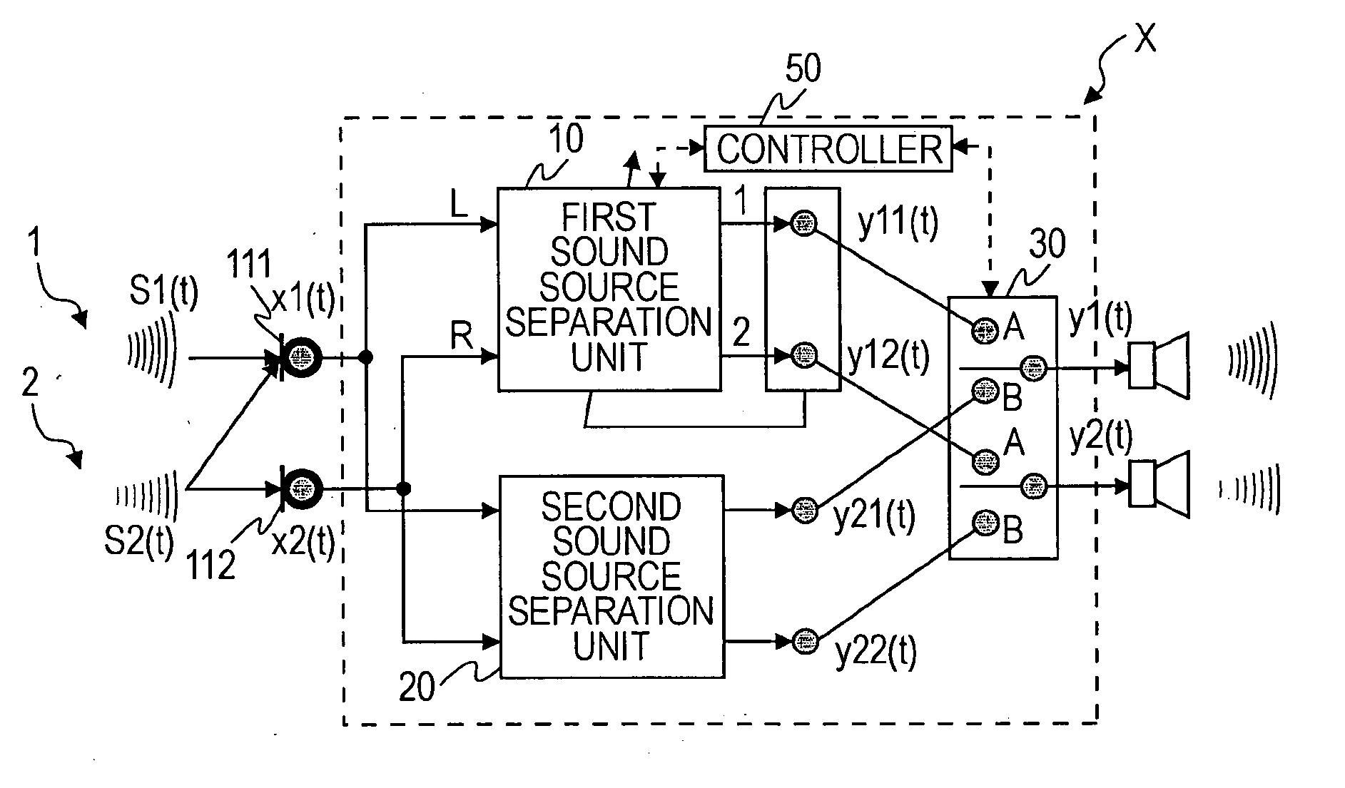
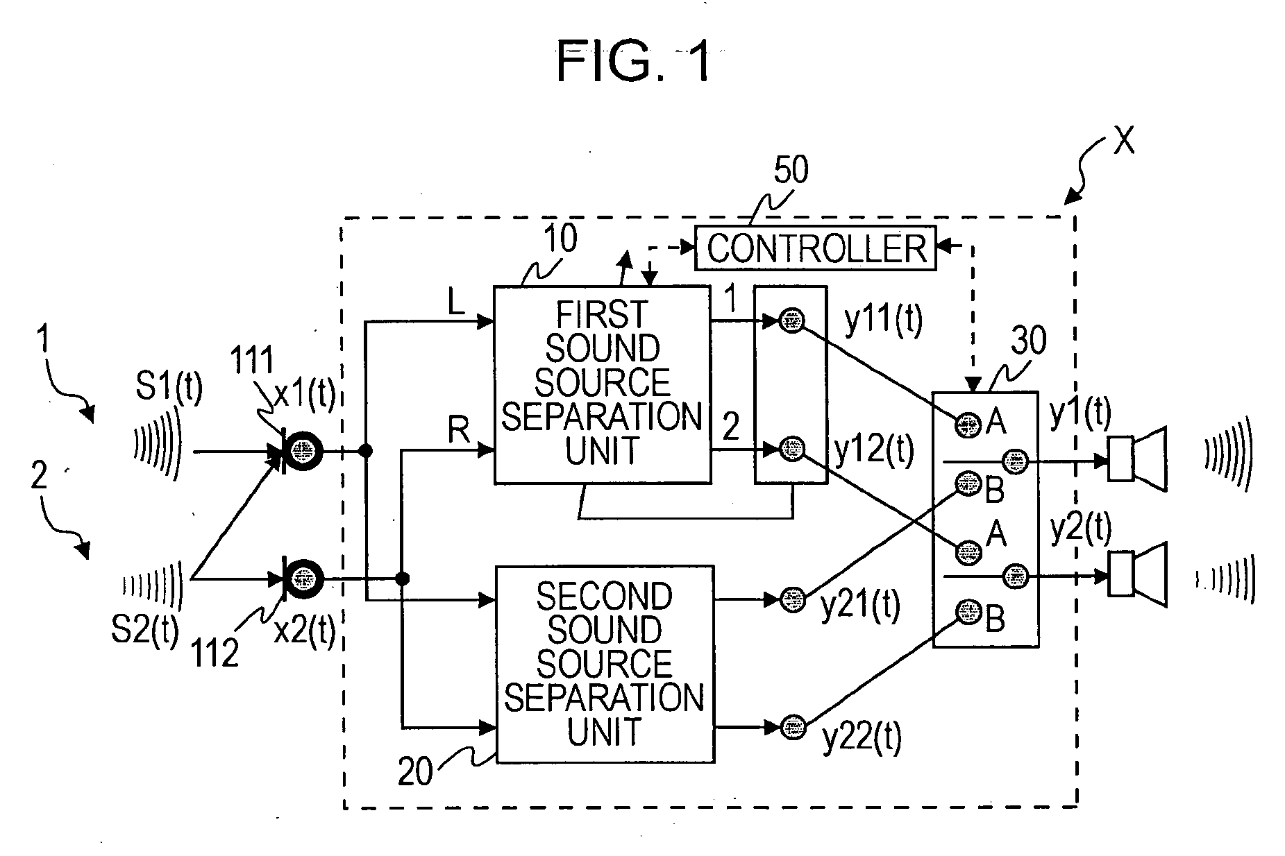
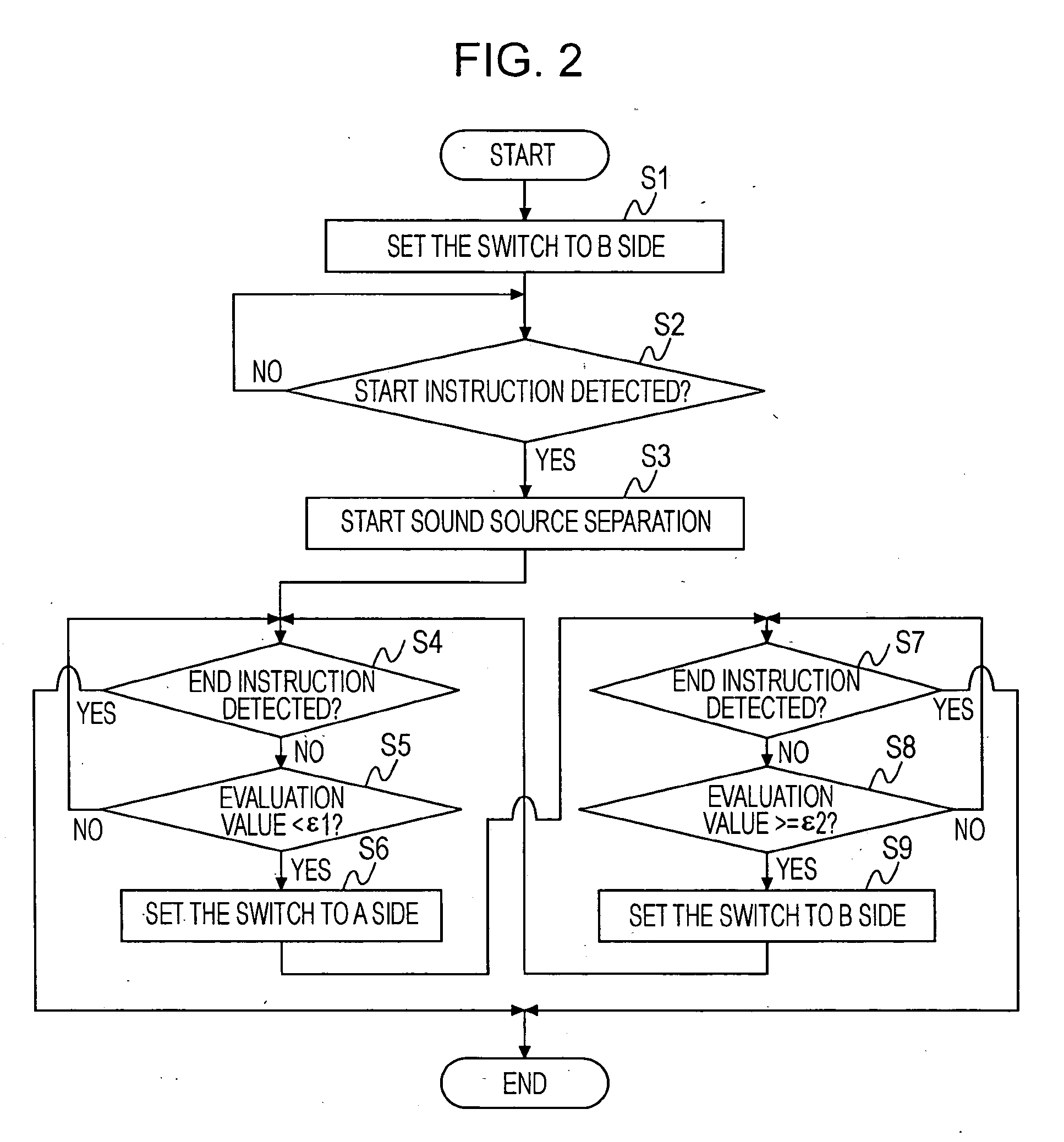
[0034]FIG. 1 is a block diagram of a sound source separation apparatus X according to an embodiment of the present invention. FIG. 2 is a flowchart illustrating sound source separation performed by the sound source separation apparatus X. FIG. 3A and FIG. 3B are time diagrams illustrating a first example of separating matrix calculations performed by a first sound source separation unit of the sound source separation apparatus X. FIG. 4A and FIG. 4B are time diagrams illustrating a second example of separating matrix calculations performed by the first sound source separation unit of the sound source separation apparatus X. FIG. 5 is a block diagram of a sound source separation apparatus Z1, ...


PUM


Abstract

A sound source separation apparatus includes a first sound source separation unit that performs blind source separation based on independent component analysis to separate a sound source signal from a plurality of mixed sound signals, thereby generating a first separated signal; a second sound source separation unit that performs real-time sound source separation by using a method other than the blind source separation based on independent component analysis to generate a second separated signal; and a multiplexer that selects one of the first separated signal and the second separated signal as an output signal. The first sound source separation unit continues processing regardless of the selection state of the multiplexer. When the first separated signal is selected as an output signal, the number of sequential calculations of a separating matrix performed in the first sound source separation unit is limited to a number that allows for real-time processing.

Description

BACKGROUND OF THE INVENTION [0001] 1. Field of the Invention [0002] The present invention relates to a sound source separation apparatus and a sound source separation method. [0003] 2. Description of the Related Art [0004] In a space that accommodates a plurality of sound sources and a plurality of microphones, each microphone receives a sound signal in which individual sound signals from the sound sources (hereinafter referred to as “sound source signals”) overlap each other. Hereinafter, the received sound signal is referred to as a “mixed sound signal”. A method of identifying (separating) individual sound source signals on the basis of only the plurality of mixed sound signals is known as a “blind source separation method” (hereinafter simply referred to as a “BSS method”). [0005] In addition, among a plurality of sound source separation processes based on the BSS method, a sound source separation process of a BSS method based on the independent component analysis method (herein...

Claims


Application Information

Patent Timeline
IPC IPC(8): H04R5/00G10L21/028
CPCG10L21/0272H04S1/007G10L2021/02166
Inventor HIEKATA, TAKASHI
Owner KOBE STEEL LTD
Why Eureka
Try Eureka