
Microphone comprising an hf transmitter

a microphone and transmitter technology, applied in the field of wireless microphone systems, can solve the problems of difficult technical problems, difficult to use, and complicated exchange operation, and achieve the effects of improving the sensitivity or the intermodulation spacing of the receiver, improving the frequency economy, and enlarge the (tunable) receiving frequency band width of the receiver

Inactive Publication Date: 2007-02-01
SENNHEISER ELECTRONICS GMBH & CO KG
View PDF12 Cites 45 Cited by
  • Summary
  • Abstract
  • Description
  • Claims
  • Application Information

AI Technical Summary

Benefits of technology

[0011] A circulator / HF isolator usually has a low level of transmission attenuation in the transmitting or receiving direction and a high level of blocking attenuation in opposite relationship to the transmitting or receiving direction respectively. The impedance at the input of the circulator / HF isolator is constant and independent of the impedance of subsequent components. In that way, in the case of transmitting devices, it is ensured that the transmitting amplifier can operate in a constant operating range. Thus for example upon touching of—and thus de-tuning of—the antenna, that results in a lower level of feedback to the transmitting amplifier or the entire transmitting device. An essential advantage of decoupling of the antenna from the transmitting amplifier by a circulator / HF isolator is that two adjacent transmitters only still slightly influence each other; intermodulation between the transmitters is greatly reduced. In that way a plurality of transmitter microphones can co-operate in an interference-free manner in a narrower frequency range. Frequency economy is improved. In the converse situation, the tuning range in which the transmitters are to operate can be increased, with the same technical properties (intermodulation products).
[0019] The particular advantages of the invention are that more transmitters than hitherto can be implemented in a frequency band, a change in frequency can be very easily effected and even existing HF transmitters, transmitting installations and also wireless microphones can be easily retro-fitted.

Problems solved by technology

It is apparent that that exchange operation is fairly complicated and expensive and often also gives rise to difficult technical problems.

Method used


Image

  • Microphone comprising an hf transmitter
  • Microphone comprising an hf transmitter
  • Microphone comprising an hf transmitter

Examples


Embodiment Construction

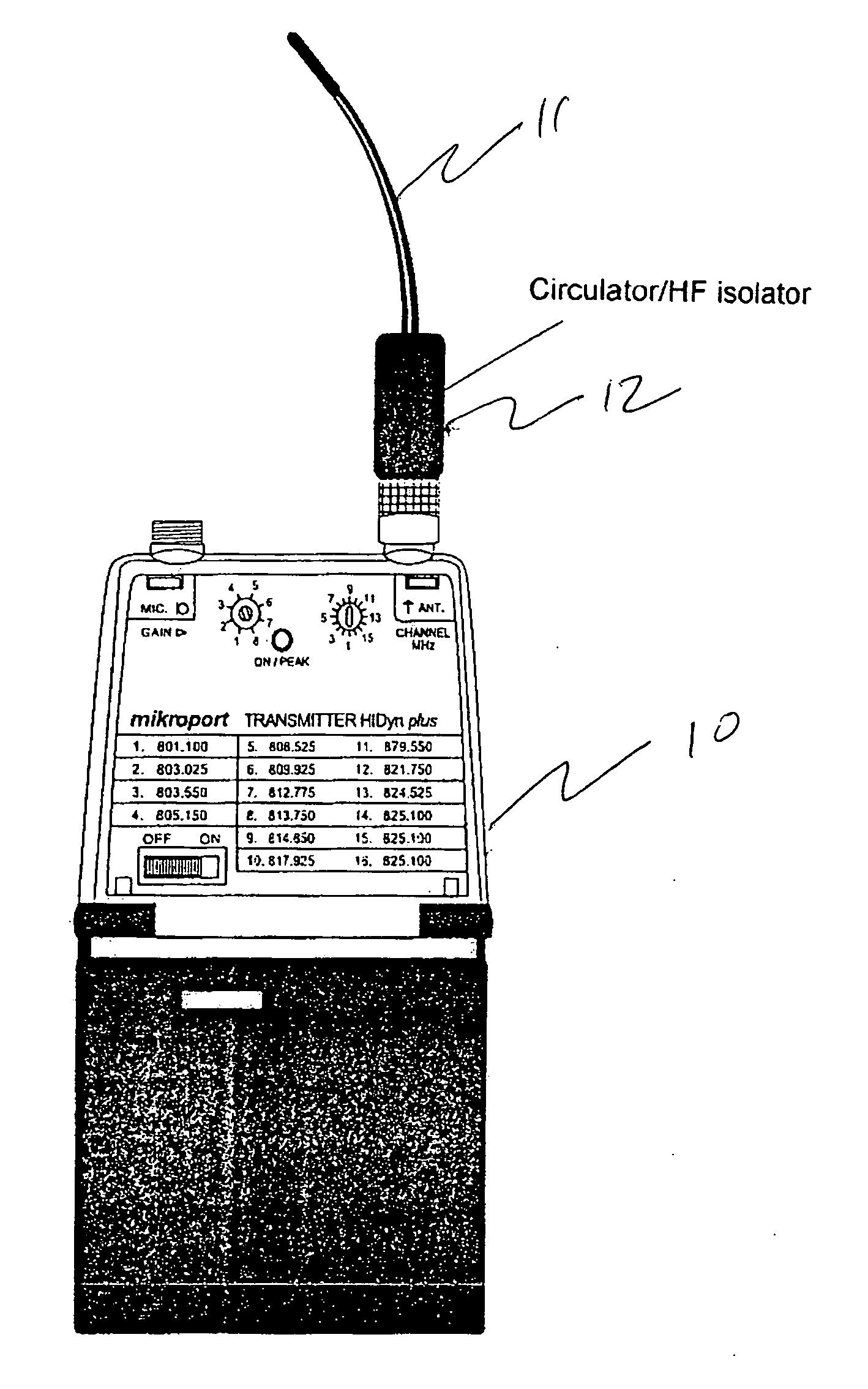
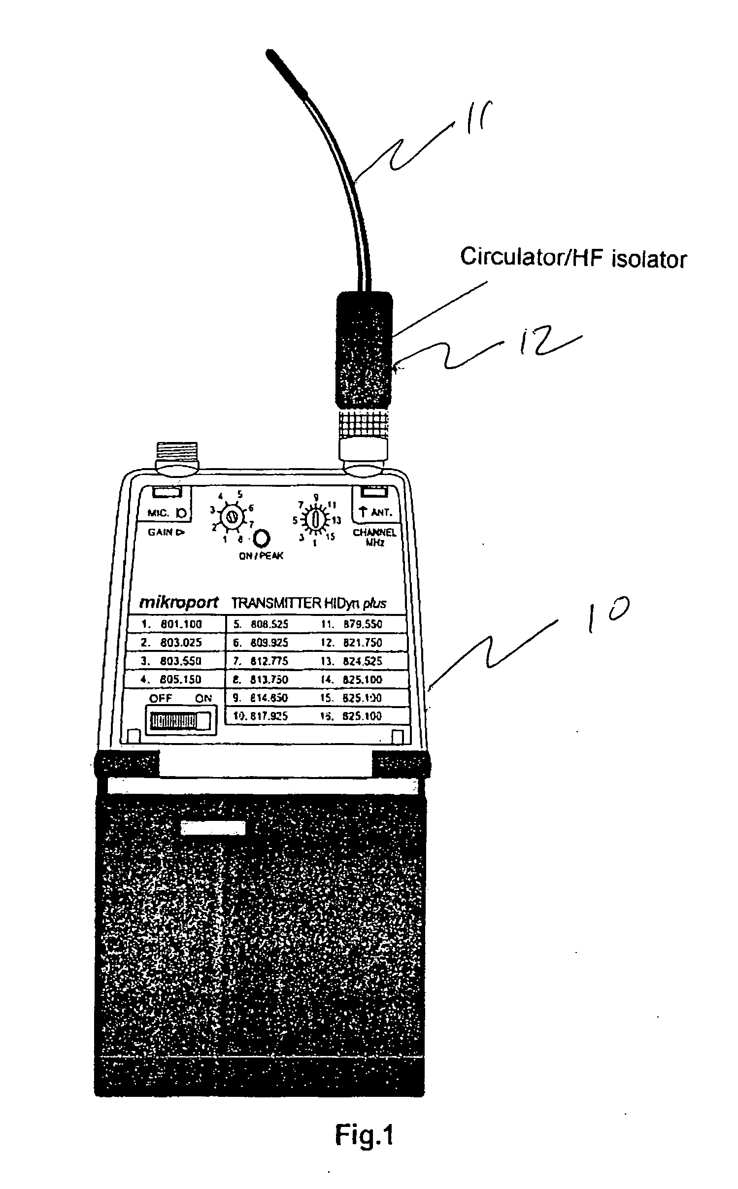
[0024] Referring once again to the figures, a transmitter 10 has an antenna 11 with a circular (HF isolator) 12 disposed in the antenna as shown in FIG. 1.

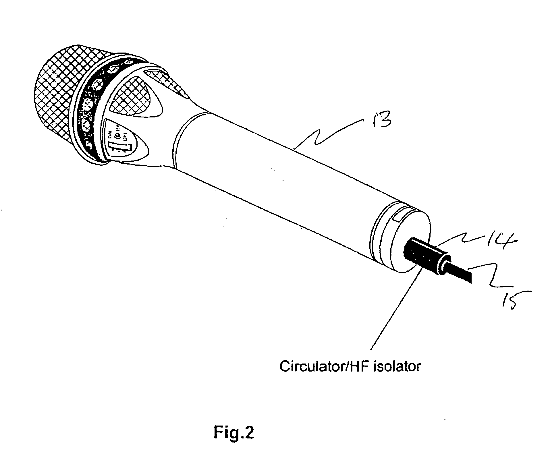
[0025] In FIG. 2, a microphone 13 is shown having an antenna 15. A circular and / or HF isolator is disposed in the antenna so that the respective frequency band can be easily set by replacement of the antenna.

[0026] Insofar as a wireless microphone system is described in the present application, it will be appreciated that this applies not only restricted thereto, but basically for an HF transmitter having an antenna.

[0027] It is also particularly advantageous for the antenna to be externally provided with an identification, that identification being associated with the respective frequency range of the circulator and / or the circulator unit. The identification can for example consist of a coding or also a color identification, so that the expert, in this case a sound technician or a sound engineer, can already very readily recog...


PUM


Abstract

The invention concerns a wireless microphone system. The object of the present invention is to further develop such wireless microphone systems. A further aim of the invention is to provide an improvement in the intermodulation spacing of HF transmitters so that more transmitters can be used in the same frequency band. A wireless microphone system comprising antennae connected thereto, wherein a circulator and / or an HF isolator is connected to the antennae or the antenna.

Description

CROSS-REFERENCE TO RELATED APPLICATIONS [0001] This application claims priority of International Application No. PCT / EP2004 / 003298, filed Mar. 29, 2004, and German Application No. 103 15 744.1, filed Apr. 4, 2003, the complete disclosures of which are hereby incorporated by reference. BACKGROUND OF THE INVENTION [0002] a) Field of the Invention [0003] The invention concerns a wireless microphone system. [0004] b) Description of the Related Art [0005] Such wireless microphones are already used in many different ways. In that respect attention is to be directed to the catalog from Lectrosonics Inc, USA: UHF Wireless Microphone Catalog 03 / 03, page 4, U.S. Pat. No. 4,430,619 and DE 2 226 515 A. OBJECT AND SUMMARY OF THE INVENTION [0006] The primary object of the present invention is to further develop such wireless microphone systems. A further aim of the invention is to provide an improvement in the intermodulation spacing of HF transmitters so that more transmitters can be used in the...

Claims


Application Information

Patent Timeline
IPC IPC(8): H04R3/00H04B5/06H04B7/08
CPCH01Q1/088H01Q1/22H04R1/08H04B1/0458H04B7/0802H01Q1/273
Inventor FEHR, MATTHIAS
Owner SENNHEISER ELECTRONICS GMBH & CO KG
Learn More