Multi-fiber fiber optic assembly

a fiber optic and fiber optic technology, applied in the field of fiber optic assemblies, can solve the problems of inability to meet the high tensile load required for fttx installations, inability to handle mass interconnections, and inconvenient assembly of conventional receptacles and plug assemblies

Inactive Publication Date: 2007-02-01
CORNING CABLE SYST LLC
View PDF13 Cites 161 Cited by
  • Summary
  • Abstract
  • Description
  • Claims
  • Application Information

AI Technical Summary

Problems solved by technology

In addition to requiring the use of different fiber optic receptacles and plugs based upon the particular type of optical connectors, conventional receptacle and plug assemblies are typically not compact enough to accommodate high-density installations.
Current smaller assemblies, on the other hand, are not able to satisfy the high tensile loads required for FTTx installations, including the 600 lbs. drop cable pull test requirement, and are not able to handle mass interconnections.
Exposure to adverse environmental conditions is also a significant issue since current network plans suggest that receptacles may remain unoccupied (i.e., without a mated plug) for an extended period of time.
As yet however, there is an unresolved need for a compact, yet sufficiently robust fiber optic receptacle that is configured to receive only a fiber optic plug having the same type of optical fiber connector as the receptacle.
However, it is easy to get these positions (window up and window down) confused.
Therefore, there is an even further unresolved need for something that prevents obtaining an incorrect orientation.

Method used


Image

  • Multi-fiber fiber optic assembly
  • Multi-fiber fiber optic assembly
  • Multi-fiber fiber optic assembly

Examples


Embodiment Construction

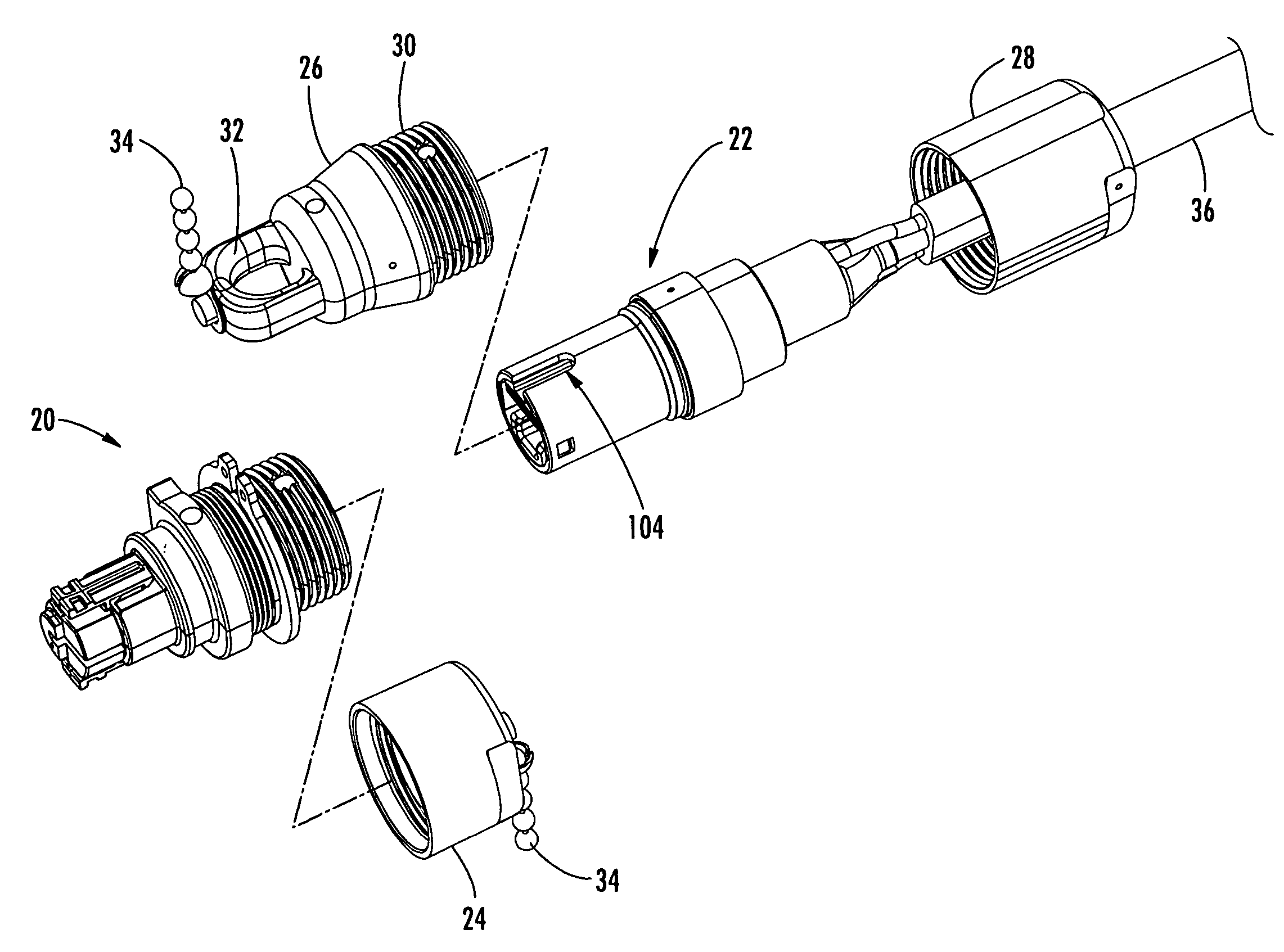
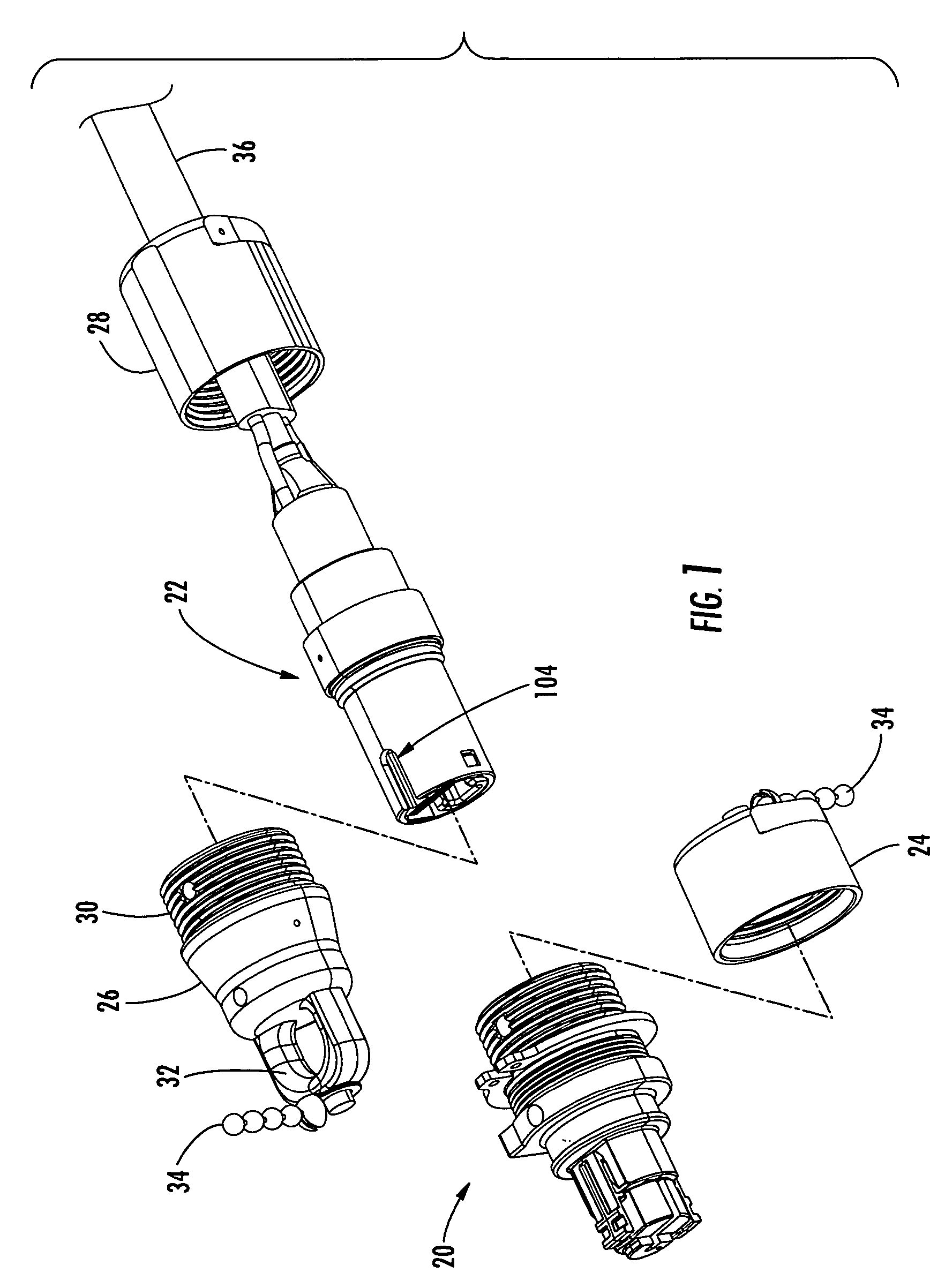
[0029] Reference will now be made in detail to the present preferred embodiments of the invention, and examples of which are illustrated in the accompanying drawings. Whenever possible, the same reference numerals will be used throughout the drawings to refer to the same or like parts. One embodiment of the multi-fiber fiber optic receptacle and plug assembly of the invention is shown in FIG. 1 with the fiber optic receptacle and corresponding fiber optic plug designated generally throughout by reference numerals 20 and 22, respectively.

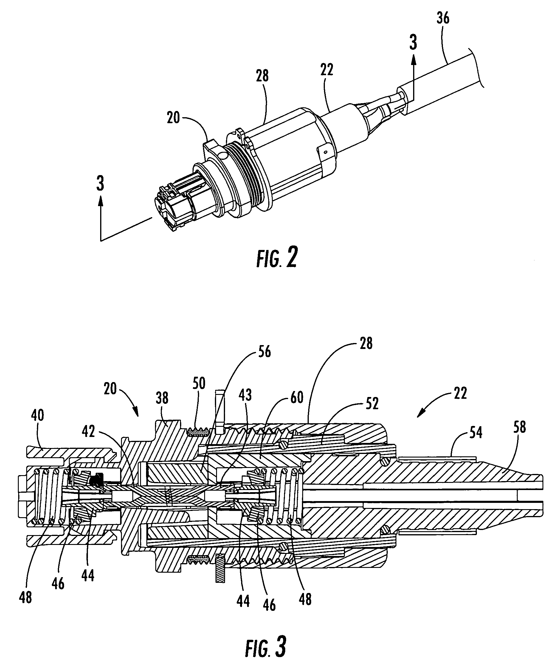
[0030] Referring now to FIGS. 1-11c, the exemplary embodiment of the fiber optic receptacle 20 and corresponding fiber optic plug 22 are shown. Although not shown, the receptacle 20 is typically mounted within a connector port defined by a wall of an enclosure, such as a connection terminal in a fiber optic communications network. In a particularly advantageous embodiment, the receptacle 20 is mounted within an opening formed through an external wal...


PUM


Abstract

A multi-fiber fiber optic assembly includes a multi-fiber fiber optic ferrule, and a keying feature on the ferrule.

Description

BACKGROUND OF THE INVENTION [0001] 1. Field of the Invention [0002] The present invention relates generally to a fiber optic assembly, and more particularly, to a multi-fiber fiber optic assembly utilizing multiple termination (MT) style ferrules for interconnecting a plurality of optical fibers within a communications network. [0003] 2. Technical Background [0004] Optical fiber is increasingly being used for a variety of broadband applications including voice, video and data transmissions. As a result, fiber optic communications networks include a number of interconnection points at which multiple optical fibers are interconnected. Fiber optic networks also include a number of connection terminals, examples of which include, but are not limited to, network access point (NAP) enclosures, aerial closures, below grade closures, pedestals, optical network terminals (ONTs) and network interface devices (NIDs). In certain instances, the connection terminals include connector ports, typic...

Claims


Application Information

Patent Timeline
Patent Type & Authority Applications(United States)
IPC IPC(8): G02B6/36G02B6/38
CPCG02B6/3821G02B6/3849G02B6/3894G02B6/3869G02B6/3885G02B6/3851G02B6/38875
Inventor DEAN, DAVID L. JR.THEUERKORN, THOMASDREMANN, CHRISTOPHER C.
Owner CORNING CABLE SYST LLC
Why Eureka
Try Eureka