Charging Roller and Image Forming Apparatus with the Same

a charging roller and image forming technology, applied in the direction of electrographic process apparatus, instruments, corona discharge, etc., can solve the problems of increasing the cost, deteriorating the productivity, and the inability to always obtain stable charging of the image carrier, so as to achieve effective space saving, stably forming the charge gap, and preventing the effect of unsticking the first and second gap members

Inactive Publication Date: 2007-02-01
SEIKO EPSON CORP
View PDF3 Cites 12 Cited by
  • Summary
  • Abstract
  • Description
  • Claims
  • Application Information

AI Technical Summary

Benefits of technology

[0074] Since the gap members are pressed toward the image carrier by the pressing members, respectively, the gap members are further securely brought in contact with the image carrier, thereby further stably forming the charge gap. As compared to the conventional manner in which the rotary shafts of the charging roller outside of the gap members are pressed, this arrangement in which the gap members are pressed by the pressing members makes the charging roller hard to deflect in a direction apart from the image carrier. Therefore, the charge gap is effectively set to be a certain value (50 μm) or less, thereby providing further stable charge over the long term.
[0075] Since the pressing members are arranged on both ends of the cleaning member, the pressing members and the cleaning member are integrally formed. Accordingly, overall size reduction is achieved, thereby further effectively achieving space saving.
[0076] In the image forming apparatus according to the aspect of the invention, the first and second gap members composed of tape-like members are present all around the charging roller in the circumferential direction to extend in the axial direction, the one end portions, on the side entering into the contact portion relative to the image carrier, and the other end portions, on the side exiting from the contact portion relative to the image carrier, of the first and second gap members are prevented from having contact with the image carrier by the first and second gap member entrance side contact-preventing means and the first and second gap member exit side contact-preventing means even when the first and second gap members enter into the contact portions relative to the image carrier, whereby the first and second gap members are securely prevented from unsticking from the charging roller even when printing action, i.e. image forming action is conducted for a prolonged period and even when the image carrier and the charging roller are stopped from rotating when the other end portions of the first and second gap members are positioned at the contact portions relative to the image carrier. Especially when the charging roller is composed of a non-elastic member which increases the frequency of the unsticking of the gap members, the unsticking of the first and second gap members is effectively prevented. Therefore, uniform and stable charge gap can be maintained over the long term so as to provide stable charge on the image carrier, thereby providing high-quality images over the long term.
[0077] In the image forming apparatus according to the aspect of the invention, the gap members composed of tape-like members are present all around the charging roller in the circumferential direction to extend in the axial direction, the one end portions, on the side entering into the contact portion relative to the image carrier, of the gap members are prevented from having contact with the image carrier by the gap member entrance side contact-preventing means even when the gap members enter into the contact portions relative to the image carrier, whereby the gap members are securely prevented from unsticking from the charging roller even when printing action, i.e. image forming action is conducted for a prolonged period. Especially when the charging roller is composed of a non-elastic member which increases the frequency of the unsticking of the gap members, the unsticking of the gap members is effectively prevented. Therefore, uniform and stable charge gap can be maintained over the long term so as to provide stable charge on the image carrier, thereby providing high-quality images over the long term.

Problems solved by technology

Accordingly, it is required to carry out extremely strict dimensional control of the film members, thus deteriorating the productivity and also increasing the cost.
Consequently, it is impossible to always obtain stable charging of the image carrier.
Therefore, the uniform charge on the photoconductive drum “f” by the charging roller “a” is impossible.
There is a problem that it is difficult to obtain stable charge.
Especially, this problem is significantly bigger in case where the charging roller “a” is composed of a non-elastic member.
However, as the circumferential environment varies or the friction coefficient between the gap member “d”, “e” and the photoconductive drum “f” varies due to adhesion of foreign matter such as toner particles to the gap members “d”, “e”, the driving torque of the photoconductive drum “f” is not effectively transmitted to the charging roller “a” so that the rotation of the charging roller “a” becomes unstable.
Especially, in case where the charging roller “a” is composed of a non-elastic member, this vibration may become strongly apparent.
This is because the non-elastic charging roller is different from the elastic charging roller made of rubber or the like in that the contact between the charging roller “a” and the photoconductive drum “f” is substantially line contact so that it is impossible to ensure enough nip pressure at the contact between the charging roller “a” and the photoconductive drum “f” and it is therefore difficult to stably drive the charging roller “a” over the long term.
In the image forming apparatus disclosed in Documents 1 and 2, however, the deflection of the photoconductive drum due to the pressure of the charging roller can not be effectively prevented because the transfer roller is just arranged in the region opposite to the charging roller relative to the perpendicular line.
In the image forming apparatus disclosed in Documents 1 and 2, therefore, it is difficult to readily obtain the high-precision charge gap which is uniform in the axial direction.
Further, when the film members as the gap members “d”, “e” are just wrapped around the peripheral surface of the charging roller “a” in the manner as the charging roller disclosed in Document 1, there is a problem that, as the pressure contact between the gap members “d”, “e” and the photoconductive drum is repeated, at least one of the ends of the gap members “d”, “e” unstick and ride up from the photoconductive drum.
Therefore, it is difficult to conduct uniform and stable charge relative to the photoconductive drum.
As compared to the conventional manner in which the rotary shafts of the charging roller outside of the gap members are pressed, this arrangement in which the gap members are pressed by the pressing members makes the charging roller hard to deflect in a direction apart from the image carrier.

Method used


Image

  • Charging Roller and Image Forming Apparatus with the Same
  • Charging Roller and Image Forming Apparatus with the Same
  • Charging Roller and Image Forming Apparatus with the Same

Examples


first embodiment

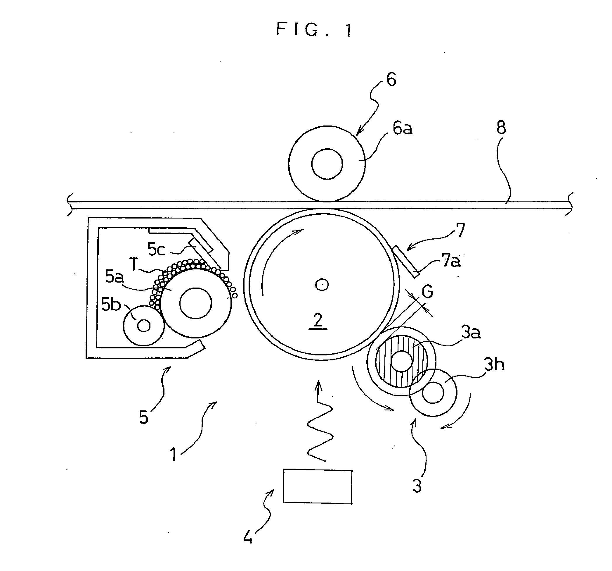
[0143]FIG. 1 is an illustration schematically and partially showing an image forming apparatus of a first embodiment according to the invention.

[0144] As shown in FIG. 1, the image forming apparatus 1 of this embodiment comprises a photoconductor 2 as an image carrier on which a electrostatic latent image and a toner image are formed and further comprises, in order of the rotational direction (clockwise direction as seen in FIG. 1) of the photoconductor 2 from the upstream, a charging device 3, an optical writing device 4, a developing device 5, a transfer device 6, and a cleaning device 7 which are arranged around the photoconductor 2.

[0145] The photoconductor 2 of this embodiment is composed of a photoconductive drum. Similarly to a conventionally known photoconductive drum, the photoconductor 2 comprises a cylindrical metal tube and a photoconductive layer having a predetermined film thickness covering the peripheral surface of the metal tube. As the metal tube of the photocondu...

fifth embodiment

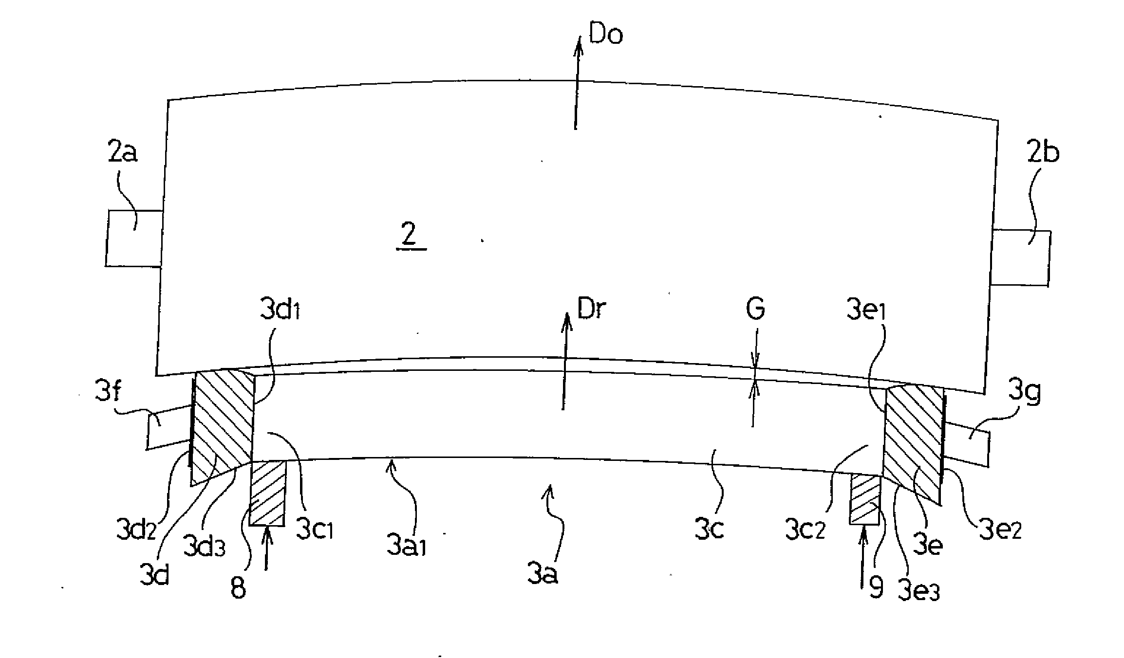
[0204]FIG. 7 is an illustration schematically showing a photoconductor and a charging roller in an image forming apparatus of a fifth embodiment according to the invention.

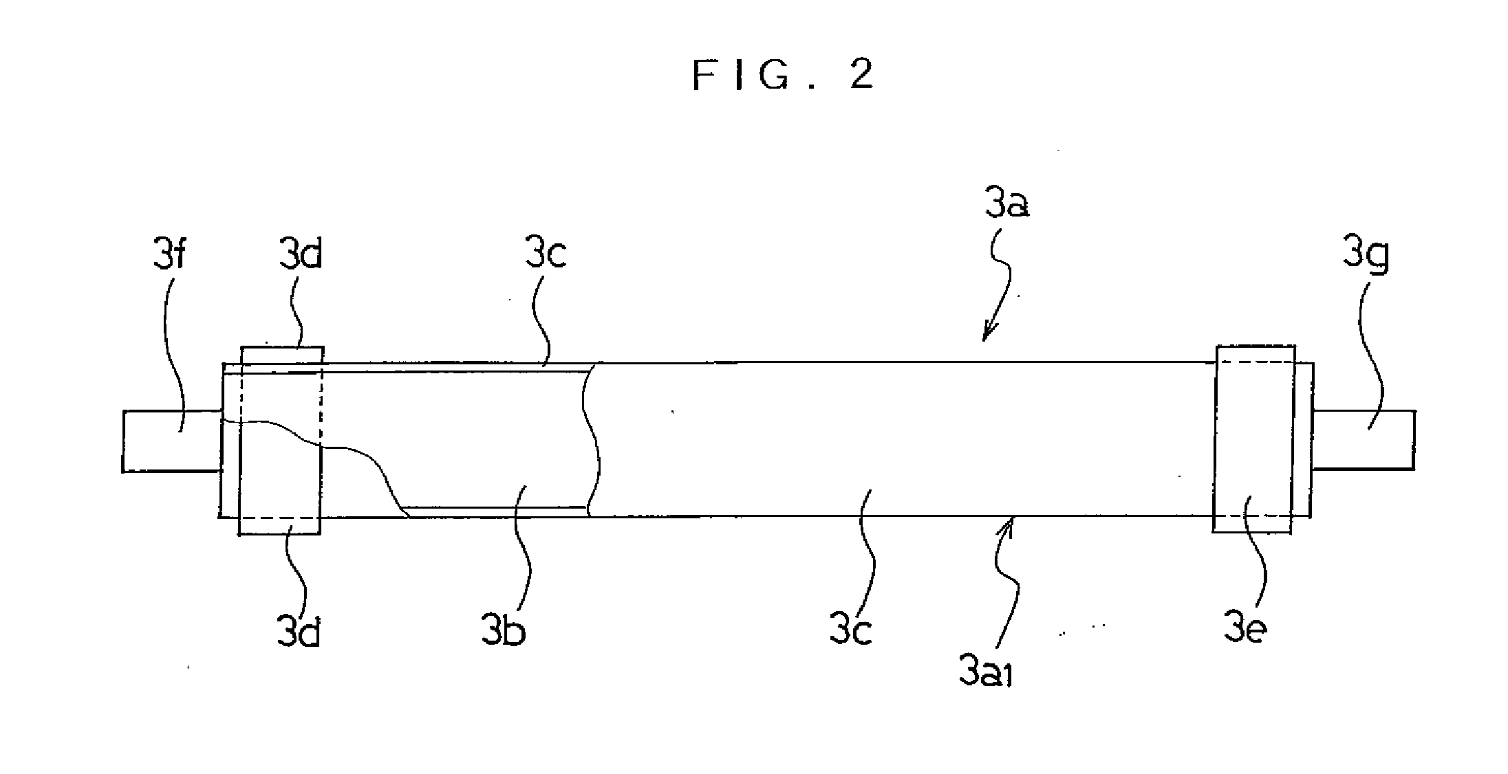
[0205] As shown in FIG. 7, a charging roller 3a of the fifth embodiment A comprises a metal core 3b and a resistive layer 3c which is formed on the peripheral surface of the metal core 3b by spraying conductive coating material. On the resistive layer 3c, gap members 3d, 3e composed of electrical insulating tape-like film members are fixed to and wound into ring-like shape around the peripheral surfaces of both end portions of the resistive layer 3c. The charging roller 3a comprises rotary shafts 3f, 3g coaxially projecting from the both ends of the metal core 3b in the axial direction. The rotary shafts 3f, 3g are rotatably supported on the apparatus body by bearings.

[0206] The gap members 3d, 3e sets a predetermined charge gap G between the resistive layer 3c and the photoconductor 2 when pressed against the pe...

sixth embodiment

[0215]FIG. 8 is an illustration schematically showing a photoconductor and a charging roller in an image forming apparatus of a sixth embodiment according to the invention.

[0216] Though the pressing members 8, 9 are each of one-piece type in which the first pressing portion 8a, 9a for pressing the gap member 3d, 3e and the second pressing portion 8b, 9b for pressing the portion 3c1, 3c2 of the resistive layer 3c are integrally formed in the aforementioned image forming apparatus 1 of the fifth embodiment shown in FIG. 7, a pair of pressing members 8, 9 for pressing the end portions of the charging roller 3a are each of two-piece type in the image forming apparatus of the sixth embodiment as shown in FIG. 8.

[0217] That is, one pressing member 8 is composed of two pieces, that is, a first pressing member 8′ for pressing the gap member 3d and a second pressing member 8″, which is a separate member from the first pressing member 8, for pressing the portion 3c1 of the resistive layer 3c...


PUM


Abstract

An image forming apparatus comprises: at least an image carrier of which rotary shafts extending from both ends thereof are rotatably supported on an apparatus body by bearings; and a charging roller having gap members fixed to both end portions thereof, respectively, wherein the gap members are brought in contact with the peripheral surface of the image carrier with some pressure to form a charge gap between the image carrier and the charging roller so that the charging roller charges the image carrier in non-contact state with the charge gap, and wherein the gap members are each formed to have a small-diameter portion on the inside thereof and a large-diameter portion on the outside thereof such that the respective small-diameter portions are positioned to face each other.

Description

CROSS-REFERENCE TO RELATED APPLICATIONS [0001] This application is based upon and claims the benefit of priority from prior Japanese Patent Application No. 2005-222908, filed Aug. 1, 2005, Japanese Patent Application No. 2005-222907, filed Aug. 1, 2005, Japanese Patent Application No. 2005-222910, filed Aug. 1, 2005, Japanese Patent Application No. 2005-222911, filed Aug. 1, 2005, Japanese Patent Application No. 2005-222909, filed Aug. 1, 2005, Japanese Patent Application No. 2005-248741, filed Aug. 30, 2005, Japanese Patent Application No. 2005-248740, filed Aug. 30, 2005, the entire contents of which are incorporated herein by reference. BACKGROUND [0002] 1. Technical Field [0003] The present invention relates to a technology of a charging roller having ring-like gap members or gap members composed of tape-like film members fixed to both end portions thereof to form a predetermined charge gap relative to an image carrier so that the charging roller charges the image carrier in non...

Claims


Application Information

Patent Timeline
Patent Type & Authority Applications(United States)
IPC IPC(8): G03G15/00G03G15/02
CPCG03G15/0291G03G15/0208
Inventor KAMOSHIDA, SHINICHIKITAZAWA, ATSUNORIMIZUTANI, TADAHIROIKUMA, KENOHASHI, KAZUYOSHI
Owner SEIKO EPSON CORP
Why Eureka
Try Eureka