
Method and apparatus for link adaptation

Inactive Publication Date: 2007-02-01
TELEFON AB LM ERICSSON (PUBL)
View PDF7 Cites 106 Cited by
  • Summary
  • Abstract
  • Description
  • Claims
  • Application Information

AI Technical Summary

Benefits of technology

[0018] One advantage of the present invention is that the Tx-unit does not need to have full knowledge of the receiver characteristics of the Rx-unit. Also, the link quality report may be transmitted over only one control channel and yet optimize the link performance. Also, it is possible to introduce other receiver characteristics of the Rx-unit without updating the Tx-unit, as all corrections of the link quality measure is made at the receiving unit. Also, one Tx-unit may serve several Rx-units having different receiver characteristics with optimized performance although the Tx-unit does not have full knowledge of the characteristics of any of the receivers.
[0019] Further preferred embodiments of the invention are defined in the dependent claims.
[0020] It should be emphasized that the term “comprises / comprising ” when used in this specification is taken to specify the presence of stated features, integers, steps or components but does not preclude the presence or addition of one or more other features, integers, steps, components or groups thereof.

Problems solved by technology

A typical radio link exhibits e.g. fading and interference, which results in a signal-to-interference ratio (SIR) level that changes with time.
Discrepancies between adaptation parameter settings relating to a certain link quality at the Tx-unit and the Rx-unit, respectively, may lead to a SIR loss and a crippled performance gain of advanced receiver structures, which are meant to improve the peak rate of the receiver.
Link adaptation systems are best effort systems, and unmatched Tx- / Rx-unit characteristics lead to non-optimum performance, which may be directly reflected on the experienced peak rate.
The inherent problem with all link adaptation systems is how the Tx-unit should be aware of in what way the Rx-unit experiences the radio link quality.
However, the Tx-unit does not know which TFRC it should use to optimize the link performance since the receiver characteristics known to the Tx-unit and the actual receiver characteristics of the Rx-unit might not necessarily be the same, since a particular receiver's characteristics usually is not known at the Tx-unit.
However, it is not certain that the requested TFRC matches the actual transport need.
Hence the Tx-unit is faced with a TFRC selection problem: the Tx-unit chooses the TFRC that best matches the reported TFRC indicator with respect to SIR.
However, it is not certain that the Tx-unit chooses the optimum TFRC for each particular Rx BLER (BLock Error Ratio) characteristic.
Consequently, there is a problem in that the Tx-unit needs to know the optimum physical-layer parameters of a certain Rx-unit for each particular physical channel state and user data size to optimize the link quality.
This optimization procedure would result in an extensive overhead and delay.
Consequently, it is not possible to implement the updates in an existing system, which only has one channel for the link quality report.
Another disadvantage with this system is that it is only possible to indicate the direction of a change of the link quality and not the actual change.

Method used


Image

  • Method and apparatus for link adaptation
  • Method and apparatus for link adaptation
  • Method and apparatus for link adaptation

Examples


first embodiment

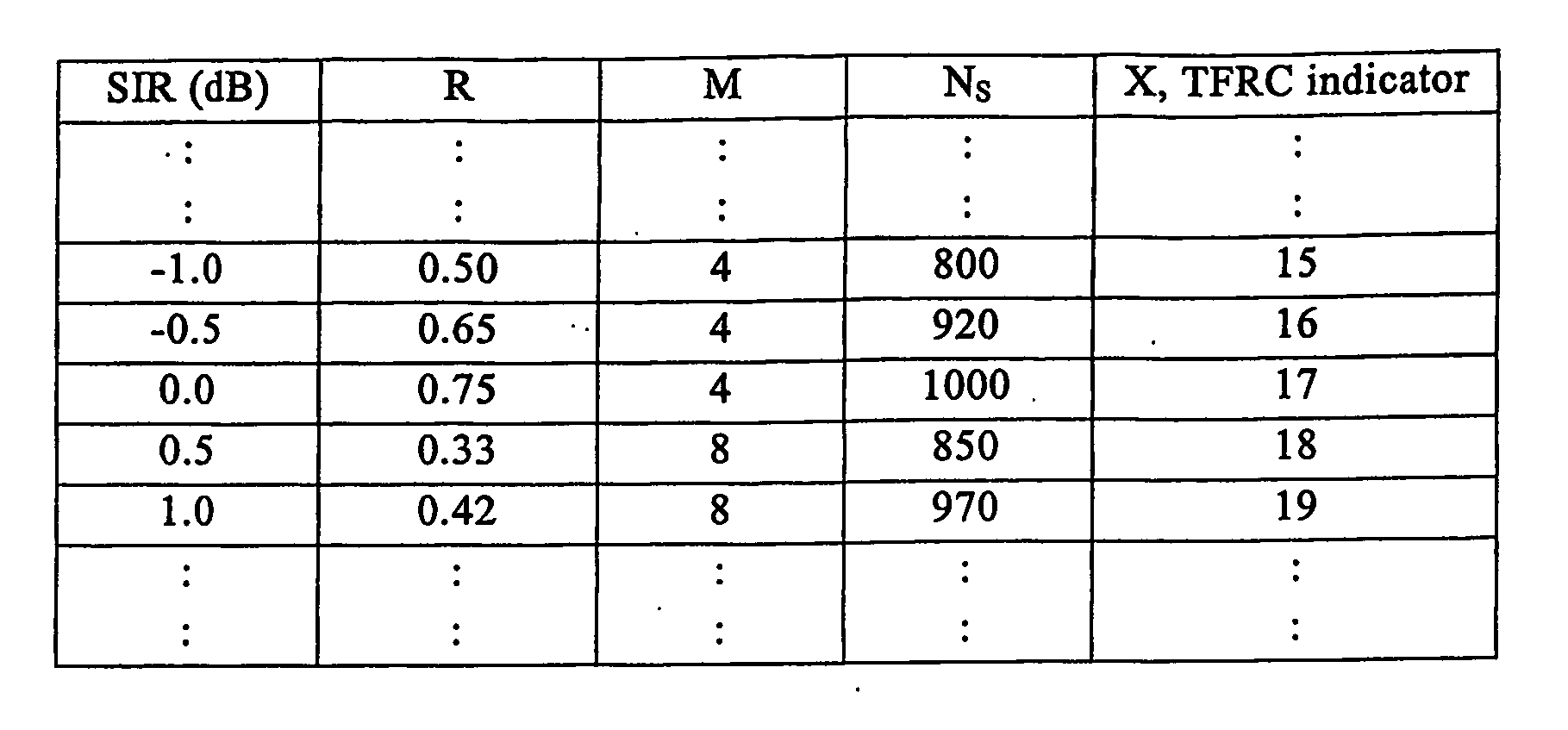
[0052] According to the invention, TFRC reporting is used. A TP indicator corresponding to a certain SIR value is reported back to the Tx-unit. For the first reporting interval of a transmission session, the measured SIR value is directly mapped against the look-up table comprising SIR values and corresponding TFRC indicators. The lookup-table may e.g. correspond to the table of FIG. 2 without the R and M columns, and be stored in the memory 33. The Rx mapping will convert the measured link quality measure for reporting interval n, such as the SIR value, to a TFRC indicator desired by the Rx-unit, or:

TnRx=fRx(γnRx, Nspec).

The user data size Ns, which will be used by the Tx-unit in a future transmission, is not known by the Rx-unit. Therefore, a value Nspec is known beforehand to both the Rx-unit and the Tx-unit. The TFRC indicator, together with Nspec when appropriate, is for the first reporting interval transmitted to the Tx-unit without any correction.

[0053] When the Tx-unit re...

third embodiment

[0060] According to the invention, the Rx-unit will take care of SIR losses although the TFRC setting at the Tx-unit is not constant during a reporting interval. An advanced scheduler, e.g. as envisaged for UMTS / HS-DSCH, may change the transmission parameter settings and thus the SIR away from the SIR that corresponds to the desired value indicated in the link quality report in order to optimize the performance of the system. Such a scheduler may e.g. use a high code rate and increase the power in case there is a shortage of physical channels to obtain a high data rate. The advanced scheduler may also use a low code rate in case the power is limited but there are physical channels, i.e channelization codes in UMTS / HS-DSCH, available for use.

[0061] The link quality report of the third embodiment may either correspond to a TFRC indicator or a SIR value, according to the previous embodiments. For convenience, reference will only be made to a TFRC reporting below. The Tx-unit will recei...


PUM


Abstract

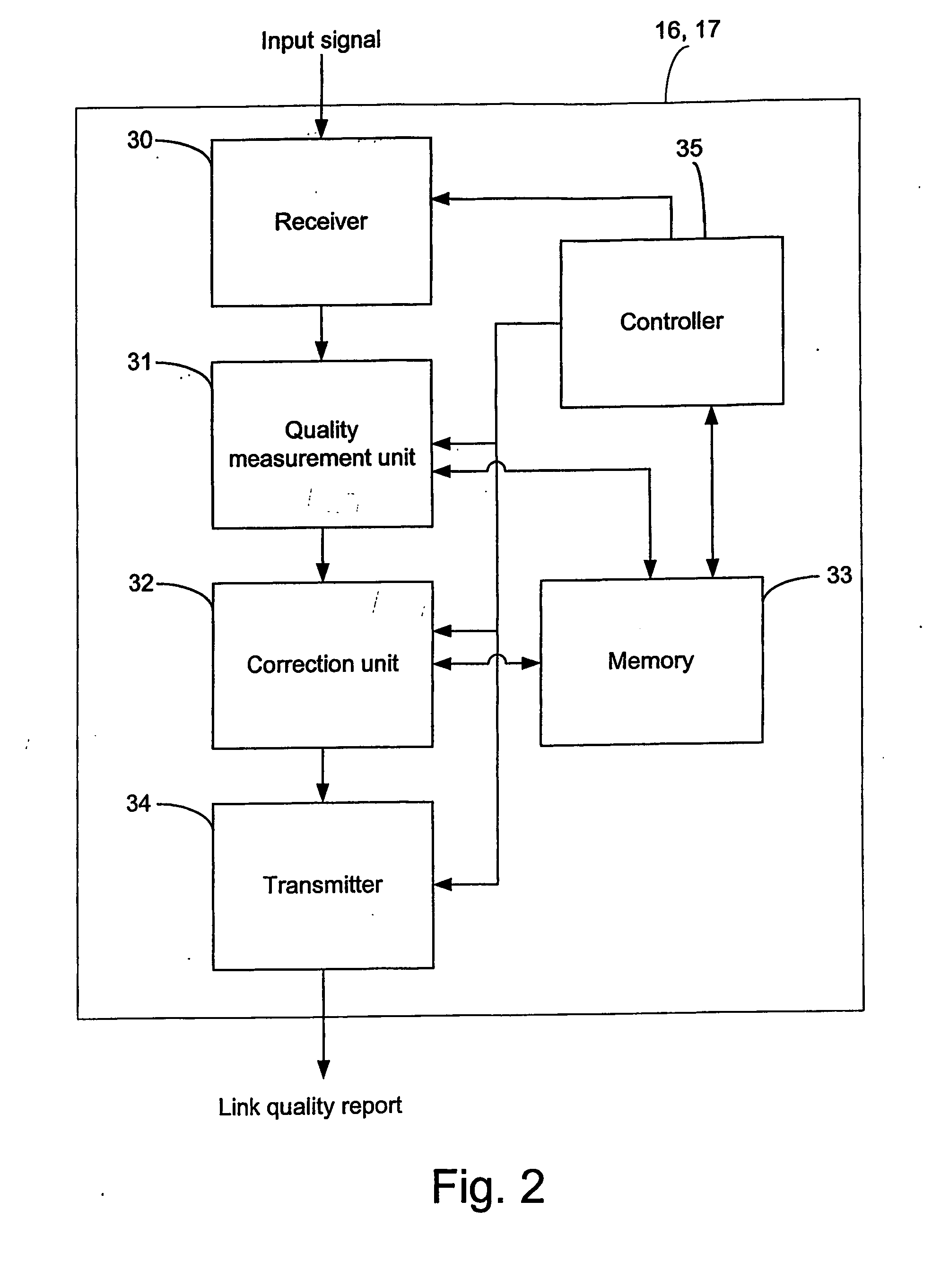
A method and apparatus for providing a link quality report in a wireless communication system supporting link adaptation. An input signal carrying data blocks in one or several transmission intervals of a reporting interval is received by a receiver of the apparatus. A quality measurement unit provides a link quality measure of the current reporting interval. A correction unit corrects the link quality measure by determining a SIR loss of the link, which is induced by unmatched transmission parameter settings of a physical layer. Then, a link quality report for the current reporting interval is based on the corrected link quality measure and transmitted by the transmitter to the transmitting unit, which will adapt the setting of physical layer parameters accordingly.

Description

TECHNICAL FIELD OF THE INVENTION [0001] The present invention relates to the field of communication systems wherein adaptation of transmission parameters is provided over time. More specifically, the invention relates to a method and an apparatus used in a communication system for optimizing the link performance between unmatched transmitter and receiver units when a link quality report is utilized for the adaptation process. DESCRIPTION OF RELATED ART [0002] In wireless communication systems, such as mobile telecommunications systems, a transmitter unit, e.g. a base station, communicates data packets and voice to a receiver unit, e.g. a portable radio communication apparatus such as a mobile radio terminal, a mobile telephone, a pager, a communicator, i.e. an electronic organizer, a smart phone or the like. In many communication systems, link adaptation, or adaptive modulation, is an established technique to adapt physical layer (L1) transmission parameters to the changing characte...

Claims


Application Information

Patent Timeline
IPC IPC(8): H04B1/00H04B7/005H04B17/00H04L1/00H04L1/20
CPCH04L1/0016H04L1/0026H04L1/0033H04L1/20H04B17/336H04W52/223H04W52/24H04W52/241H04B17/21H04W52/16
Inventor MALM, PETER
Owner TELEFON AB LM ERICSSON (PUBL)
Learn More