Method and device in UE and base station used for dynamic scheduling

a dynamic scheduling and transmission method technology, applied in the direction of signal allocation, digital transmission, transmission path sub-channel allocation, etc., can solve the problem that the design requirement of nr cannot be met by the interleaver design of the pdcch in lte, and achieve the effect of reducing the probability of blocking, maximizing the frequency diversity gain, and uniform distribution of frequency domain resources

Active Publication Date: 2020-06-30
SHANGHAI QIYU COMM TECH SERVICE CENT
View PDF3 Cites 4 Cited by
  • Summary
  • Abstract
  • Description
  • Claims
  • Application Information

AI Technical Summary

Benefits of technology

[0063]In one embodiment, compared with the interleaver design for the PDCCH in LTE, the present disclosure mainly has the following technical benefits.
[0064]According to the present disclosure, the interleaved PDCCH pattern is related to the number of REG bundles in a resource pool configured to transmit the PDCCH and the number of REs in the REG bundle. It can be guaranteed that the REG bundles constituting the PDCCH, after being interleaved, are more evenly distributed in frequency domain resources compared with the interleaving method in LTE. The frequency diversity gain is maximized.
[0065]According to the present disclosure, when distributed and localized PDCCHs share the same resource pool, the even distribution of REG bundles can effectively reduce the blocking probability during the PDCCH transmission of multiple UEs and improve the capacity of the control channel.
[0066]According to the present disclosure, compared with the cyclic shift performed only based on a cell ID in LTE, the cyclic shift performed based on the time-frequency position of the resource pool or the UE ID after the REG bundle-based interleaving can more flexibly control the randomization of interference, thereby further improving the link performance of the PDCCH transmission.

Problems solved by technology

On the other hand, due to the limit of the REG bundle, the minimum possible unit for the interleaver of the PDCCH in NR can be an REG bundle only, rather than an REG Furthermore, since the number of REs included in the REG bundle is far greater than the number of REs in the REG of the LTE PDCCH, meanwhile the bandwidth of the PDCCH in NR is far greater than the bandwidth that can be occupied by the PDCCH, the interleaver design for the PDCCH in LTE cannot meet the design requirement of NR.

Method used


Image

  • Method and device in UE and base station used for dynamic scheduling
  • Method and device in UE and base station used for dynamic scheduling
  • Method and device in UE and base station used for dynamic scheduling

Examples


embodiment 1

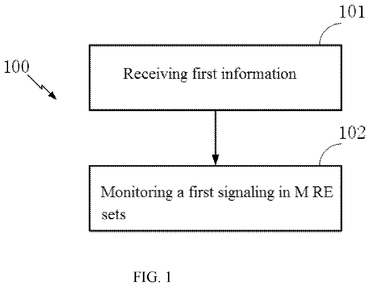
[0081]Embodiment 1 illustrates an example of a flowchart of the transmission of first information and a first signaling according to one embodiment of the present disclosure, as shown in FIG. 1. In FIG. 1, each box represents one step. In Embodiment 1, the UE in the present disclosure first receives first information and then monitors a first signaling in M RE sets, wherein the first information is used for determining the M RE sets, a monitor of the first signaling assumes that P modulation symbol groups are one-to-one mapped to P RE sets, the P RE sets are P RE sets of the M RE sets, and one blind detection for the first signaling is performed on the P RE sets; modulation symbols obtained by modulating the bits in a first bit sequence constitute a first modulation symbol set sequentially, wherein the bits in the first bit sequence are sequentially arranged according to an output of a channel encoder; the first modulation symbol set is divided into the P modulation symbol groups su...

embodiment 2

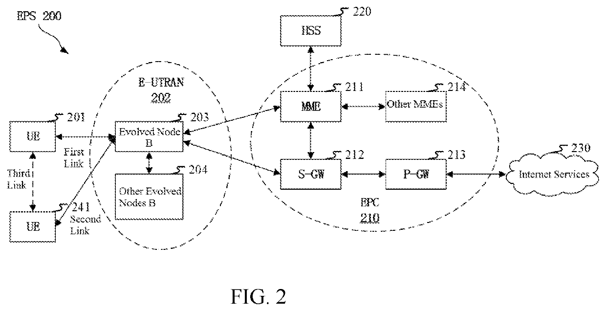
[0121]Embodiment 2 illustrates an example of a diagram of a network architecture according to the present disclosure, as shown in FIG. 2. FIG. 2 is a diagram illustrating a system network architecture 200 of NR 5G, Long-Term Evolution (LTE), Long-Term Evolution Advanced (LTE-A). The NR 5G or LTE network architecture 200 may be called an Evolved Packet System (EPS) 200. The EPS 200 may include one or more UEs 201, an NG-RAN 202, an Evolved Packet Core / 5G-Core Network (EPC / 5G-CN) 210, a Home Subscriber Server (HSS) 220 and an Internet Service 230. Herein, the EPS may be interconnected with other access networks. For simple description, the entities / interfaces are not shown. As shown in FIG. 2, the EPS provides packet switching services. Those skilled in the art are easy to understand that various concepts presented throughout the present disclosure can be extended to networks providing circuit switching services or other cellular networks. The NG-RAN includes an NR node B (gNB) 203 an...

embodiment 3

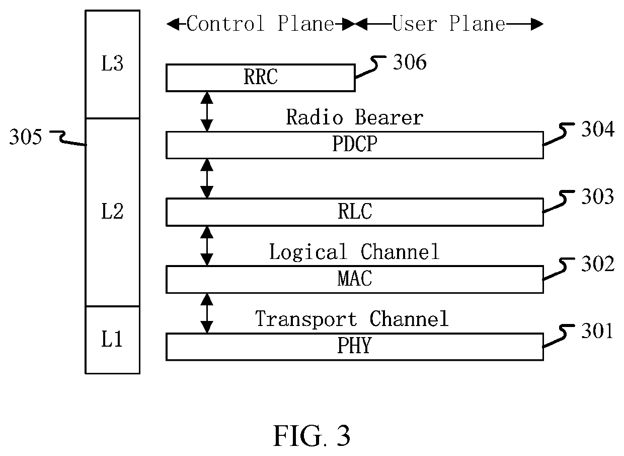
[0127]Embodiment 3 is a diagram illustrating an embodiment of a radio protocol architecture of a user plane and a control plane according to the present disclosure, as shown in FIG. 3. FIG. 3 is a diagram illustrating an embodiment of a radio protocol architecture of a user plane and a control plane. In FIG. 3, the radio protocol architecture of a UE and a gNB is represented by three layers, which are a layer 1, a layer 2 and a layer 3 respectively. The layer 1 (L1) 301 is the lowest layer and performs signal processing functions of each PHY layer. The layer 1 is called PHY 301 in this paper. The layer 2 (L2) 305 is above the PHY 301, and is in charge of the link between the UE and the gNB via the PHY 301. In the user plane, the L2 305 includes a Medium Access Control (MAC) sublayer 302, a Radio Link Control (RLC) sublayer 303, and a Packet Data Convergence Protocol (PDCP) sublayer 304. All the three sublayers terminate at the gNB of the network side. Although not described in FIG. ...


PUM


Abstract

A method and a device in a User Equipment and a base station are provided. The UE receives first information and monitors a first signaling in M Resource Element (RE) sets. The first information determines the M RE sets. The UE assumes that P modulation symbol groups are one-to-one mapped to P RE sets of the M RE sets. One blind detection for the first signaling is performed on the P RE sets. Modulation symbols obtained by modulating the bits in a first bit sequence constitute a first modulation symbol set sequentially. The bits in the first bit sequence are sequentially arranged according to an output of a channel encoder. The first modulation symbol set is successively divided into the P modulation symbol groups, each consisting of X modulation symbols. Relative positions of the P RE sets in frequency domain are related to at least one of {M, X}.

Description

CROSS REFERENCE TO RELATED APPLICATION[0001]This application claims the priority benefit of Chinese Patent Application Serial Number 201710553683.7, filed on Jul. 8, 2017, the full disclosure of which is incorporated herein by reference.BACKGROUNDTechnical Field[0002]The present disclosure relates to transmission methods and devices in wireless communication systems, and in particular to transmission schemes and devices for dynamically scheduling signaling.Related Art[0003]Application scenarios of future wireless communication systems are becoming increasingly diversified, and different application scenarios have different performance demands on systems. In order to meet different performance requirements of various application scenarios, the 3rd Generation Partner Project (3GPP) Radio Access Network (RAN) #72 plenary session decided to conduct the study of New Radio (NR). The work item of NR was approved at the 3GPP RAN #75 session to standardize the NR.[0004]In order to adapt to d...

Claims


Application Information

Patent Timeline
Patent Type & Authority Patents(United States)
IPC IPC(8): H04L5/00H04W72/12
CPCH04L5/0053H04W72/1231H04L5/0007H04L5/0091H04L5/0073H04W72/121H04W72/1263H04W72/542
Inventor ZHANG, XIAOBO
Owner SHANGHAI QIYU COMM TECH SERVICE CENT
Why Eureka
Try Eureka