Nerve protection system

a nerve protection and nerve technology, applied in the field of nerve protection systems, can solve the problems of increased nerve root fibrosis, postoperative radiculopathy, numbness and ataxia, and other side effects, and achieve the effects of reducing the risk of nerve damage, and reducing the effect of vascular damag

Inactive Publication Date: 2007-02-01
BLACKSTONE MEDICAL
View PDF6 Cites 42 Cited by
  • Summary
  • Abstract
  • Description
  • Claims
  • Application Information

AI Technical Summary

Problems solved by technology

These nerve roots are vulnerable to damage via blunt trauma, laceration, scraping, crushing, etc. during passage of the various instruments to perform discectomy, disc space preparation, and interbody placement.
It is well known that tensioning or traumatizing a nerve root can lead to post operative radiculopathy, numbness, and ataxia, among other things.
It is also understood that an increase in the exposure and manipulation of the nerve root can lead to increased nerve root fibrosis, inflammation and other side effects postoperatively.
The risk of nerve injury in general is increasing.
As a result, the access and visualization provided to the surgeon is diminishing.

Method used


Image

  • Nerve protection system
  • Nerve protection system
  • Nerve protection system

Examples


Embodiment Construction

[0014] Detailed embodiments of the present invention are disclosed herein; however, it is to be understood that the disclosed embodiments are merely illustrative of the invention that may be embodied in various forms. In addition, each of the examples given in connection with the various embodiments of the invention are intended to be illustrative, and not restrictive. Further, the figures are not necessarily to scale, some features may be exaggerated to show details of particular components. Therefore, specific structural and functional details disclosed herein are not to be interpreted as limiting, but merely as a representative basis for teaching one skilled in the art to variously employ the present invention.

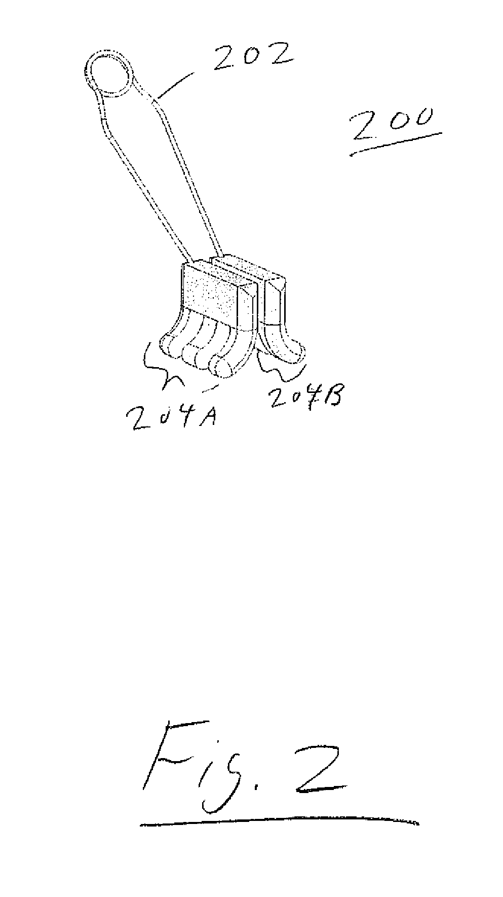
[0015] Referring now to FIG. 2, a spring loaded / specula style deployable spring clip embodiment is shown. As seen in this Fig., this embodiment may comprise a generally U-Shaped Device 200 formed of Spring Element 202 having a number of Blades 204A and 204B on the ends the...


PUM


Abstract

The present invention relates to a device (and corresponding method) that protects (e.g., shields and/or retracts) exiting and/or descending nerve (e.g., nerve root). This may be carried out in a controlled, unobtrusive manner during, for example, Transforaminal Lumbar Interbody Fusion (“TLIF”), Posterior Lumbar Interbody Fusion (“PLIF”), or Minimally Invasive Surgery (“MIS”) spinal procedures. Further, the device may be form-fit to one or more particular ones of the following: nerve, pedicle, annulus, vertebral body, interbody device.

Description

RELATED APPLICATIONS [0001] This application claims the benefit of U.S. Provisional Application Ser. No. 60 / 703,546, filed Jul. 28, 2005, which is incorporated herein by reference in its entirety.FIELD OF THE INVENTION [0002] The present invention relates to a device (and corresponding method) that protects (e.g., shields and / or retracts) exiting and / or descending nerve (e.g., nerve root). This may be carried out in a controlled, unobtrusive manner during, for example, Transforaminal Lumbar Interbody Fusion (“TLIF”), Posterior Lumbar Interbody Fusion (“PLIF”), or Minimally Invasive Surgery (“MIS”) spinal procedures. [0003] Further, the device may be form-fit to one or more particular ones of the following: nerve, pedicle, annulus, vertebral body, interbody device. BACKGROUND OF THE INVENTION [0004] In TLIF procedures using a Harms (or other) technique, the nerve roots adjacent to the spinal column are exposed by the surgical approach. The surgeon will create a channel accessing the ...

Claims


Application Information

Patent Timeline
Patent Type & Authority Applications(United States)
IPC IPC(8): A61B1/32
CPCA61B2017/0262A61B17/025
Inventor GANNOE, JAMES RICHARDFLYNN, JOHN JOSEPH
Owner BLACKSTONE MEDICAL
Why Eureka
Try Eureka