Spinal cage implant

a technology of spinal cage and implant, which is applied in the field of spinal cage implants, can solve the problems of one or more intervertebral disc deterioration or dislocation in some way, and achieve the effect of facilitating the fusion of the device and the adjacent vertebra

Inactive Publication Date: 2007-02-01
ALTIVA CORP
View PDF45 Cites 101 Cited by
  • Summary
  • Abstract
  • Description
  • Claims
  • Application Information

AI Technical Summary

Benefits of technology

[0005] The present invention provides spinal cage implants that are substantially rectangular in shape, having a top, a bottom, two side walls, and two end walls. A cage is a structure with an internal space and an openwork frame serving a...

Problems solved by technology

These discs form a cushion between adjacent vertebrae, resisting compression along the support axis of the spinal column, but permitting limited movement between the vertebrae to provide flexibility.
Injury, disease, or othe...

Method used


Image

  • Spinal cage implant
  • Spinal cage implant
  • Spinal cage implant

Examples


Embodiment Construction

[0017] The present invention will now be described with occasional reference to various embodiments of the invention. Unless otherwise defined, all terms used herein have the same meaning as commonly understood by one of ordinary skill in the art to that this invention belongs. The terminology used in the description of the invention herein is for describing particular embodiments only, and is not intended to be limiting of the invention. As used in the description of the invention and the appended claims, the singular forms “a,”“an,” and “the” are intended to include the plural forms as well, unless the context clearly indicates otherwise.

[0018] Unless otherwise indicated, all numbers expressing units of measure as used in the specification and claims are to be understood as being modified in all instances by the term “about.” Accordingly, unless otherwise indicated, the numerical properties set forth in the following specification and claims are approximations that may vary depen...


PUM


Abstract

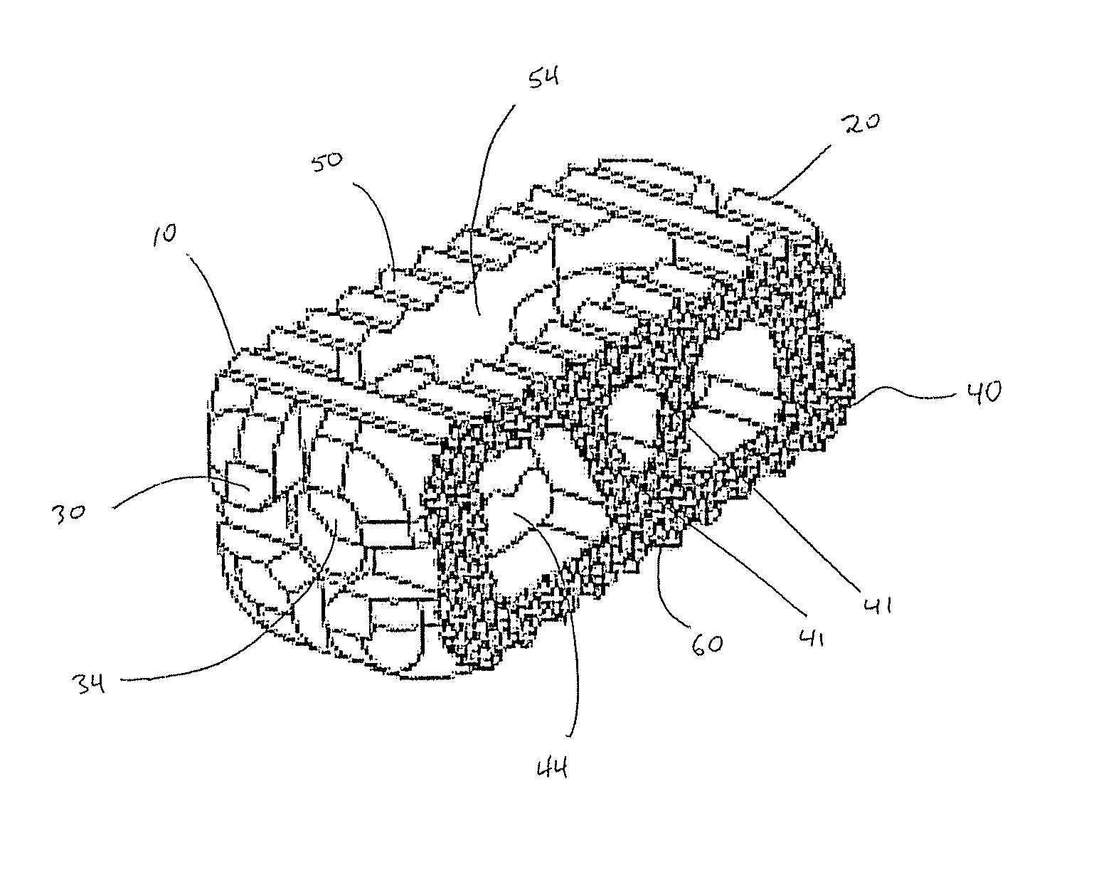
A spinal cage implant device includes a substantially planar top, a substantially planar bottom, two side walls, a posterior end wall, and an anterior end wall, wherein the implant is wider than high and longer than wide, and the substantially planar top and the substantially planar bottom include at least one opening, the external surfaces of the two side walls are textured and include at least one opening and that opening is bisected by at least one load-bearing frame structure, and at least one of the anterior end wall or posterior end wall include a hole for receiving a tool for surgical insertion of the spinal cage implant.

Description

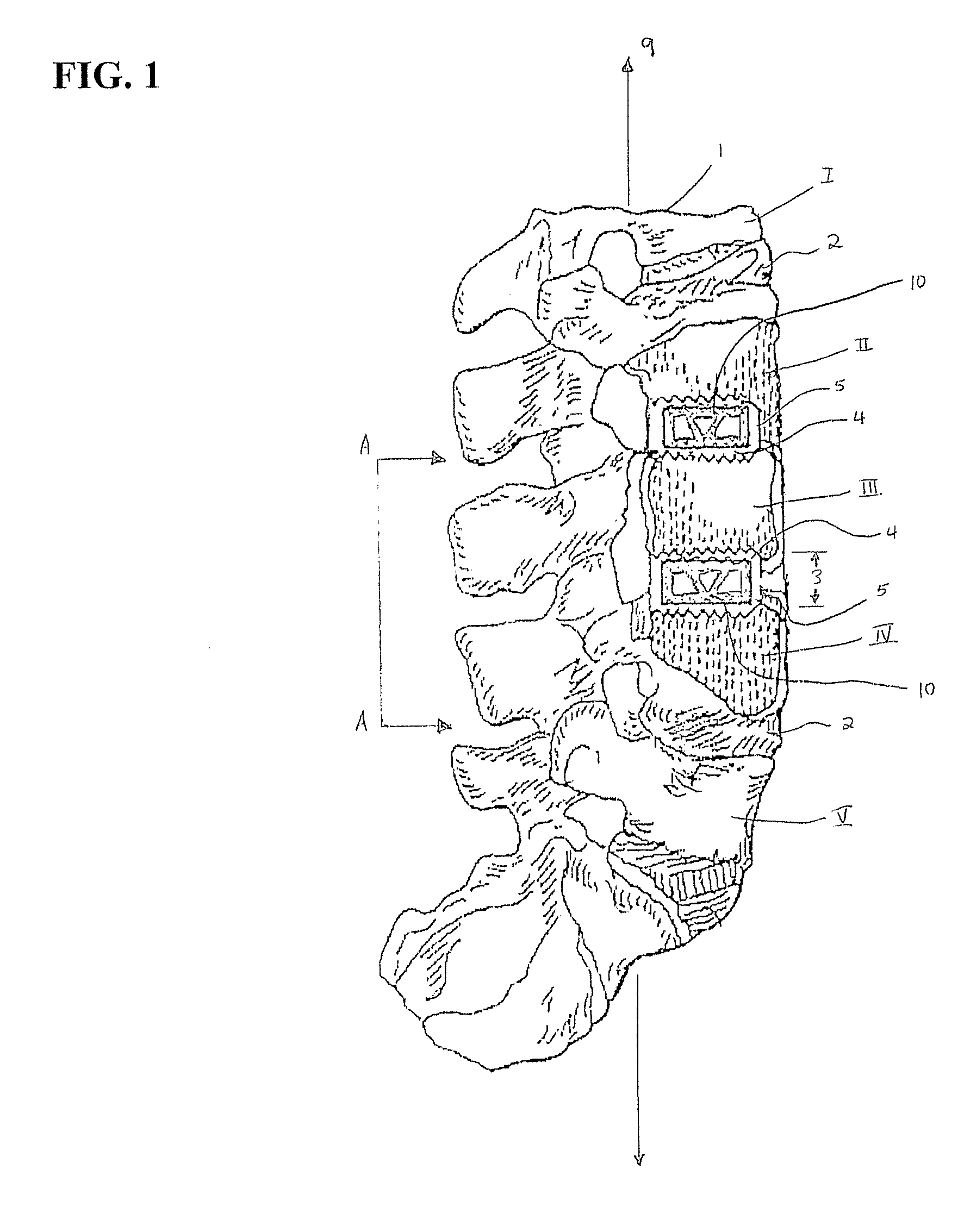
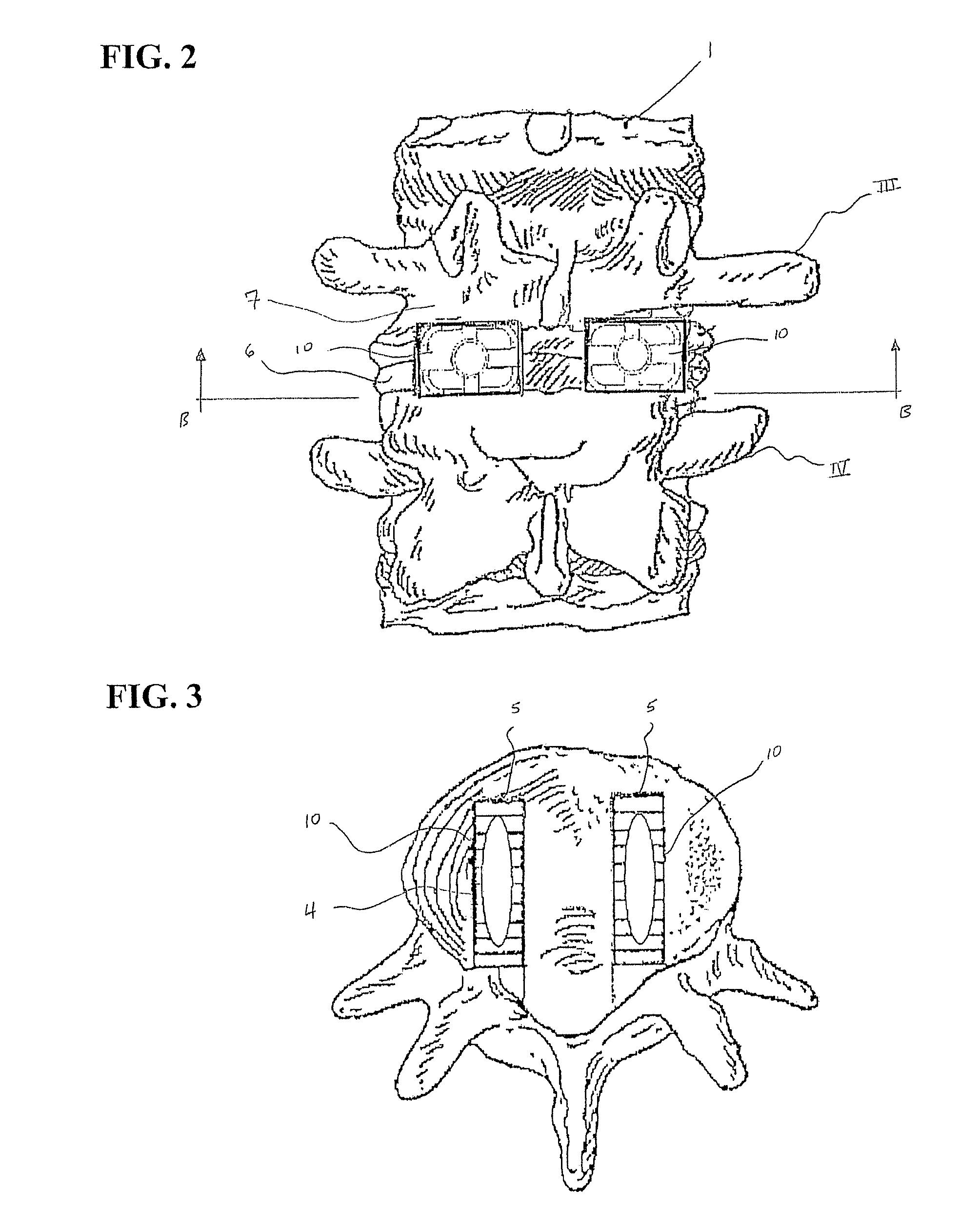
PRIORITY CLAIM [0001] This application claims priority to U.S. Provisional Patent Application No. 60 / 703,511 entitled “Spinal Cage Implant,” which was filed Jul. 28, 2005. Application No. 60 / 703,511 is incorporated herein by reference in its entirety.BACKGROUND OF THE INVENTION [0002] The spinal column is formed from a number of vertebrae that are separated from one another by cartilaginous intervertebral discs. These discs form a cushion between adjacent vertebrae, resisting compression along the support axis of the spinal column, but permitting limited movement between the vertebrae to provide flexibility. Injury, disease, or other degenerative disorders may cause one or more intervertebral discs to deteriorate or become dislocated in some way. This damage can lead to compression of adjacent nerve roots, frequently causing chronic and often disabling pain. [0003] A number of methods and associated devices have been suggested for the replacement of damaged intervertebral discs, and...

Claims


Application Information

Patent Timeline
IPC IPC(8): A61F2/44
CPCA61F2/447A61F2/4611A61F2002/2835A61F2002/30112A61F2002/30266A61F2002/30772A61F2230/0082A61F2002/30904A61F2002/4475A61F2002/448A61F2002/4629A61F2230/0004A61F2002/3082A61F2002/30593
Inventor MCCORD, DAVIDKAPITAN, JOHNBLAIN, JASON
Owner ALTIVA CORP
Why Eureka
Try Eureka