Extended failure analysis in RAID environments

a failure analysis and raid environment technology, applied in the field of storage technology, can solve the problems saving time and expense, and achieve the effect of reducing the number of working hard drives and saving time and expens

Inactive Publication Date: 2007-02-01
LSI CORPORATION
View PDF8 Cites 30 Cited by
  • Summary
  • Abstract
  • Description
  • Claims
  • Application Information

AI Technical Summary

Benefits of technology

[0014] In one embodiment, the RAID controller may issue diagnostic commands to the hard drive or enclosure to help determine if the timeout occurred due to a hardware failure in the hard drive or some other problem. If the failure was caused by a problem other than a hardware failur...

Problems solved by technology

This saves time and expense by reducing the number of functioning hard d...

Method used


Image

  • Extended failure analysis in RAID environments
  • Extended failure analysis in RAID environments
  • Extended failure analysis in RAID environments

Examples


Embodiment Construction

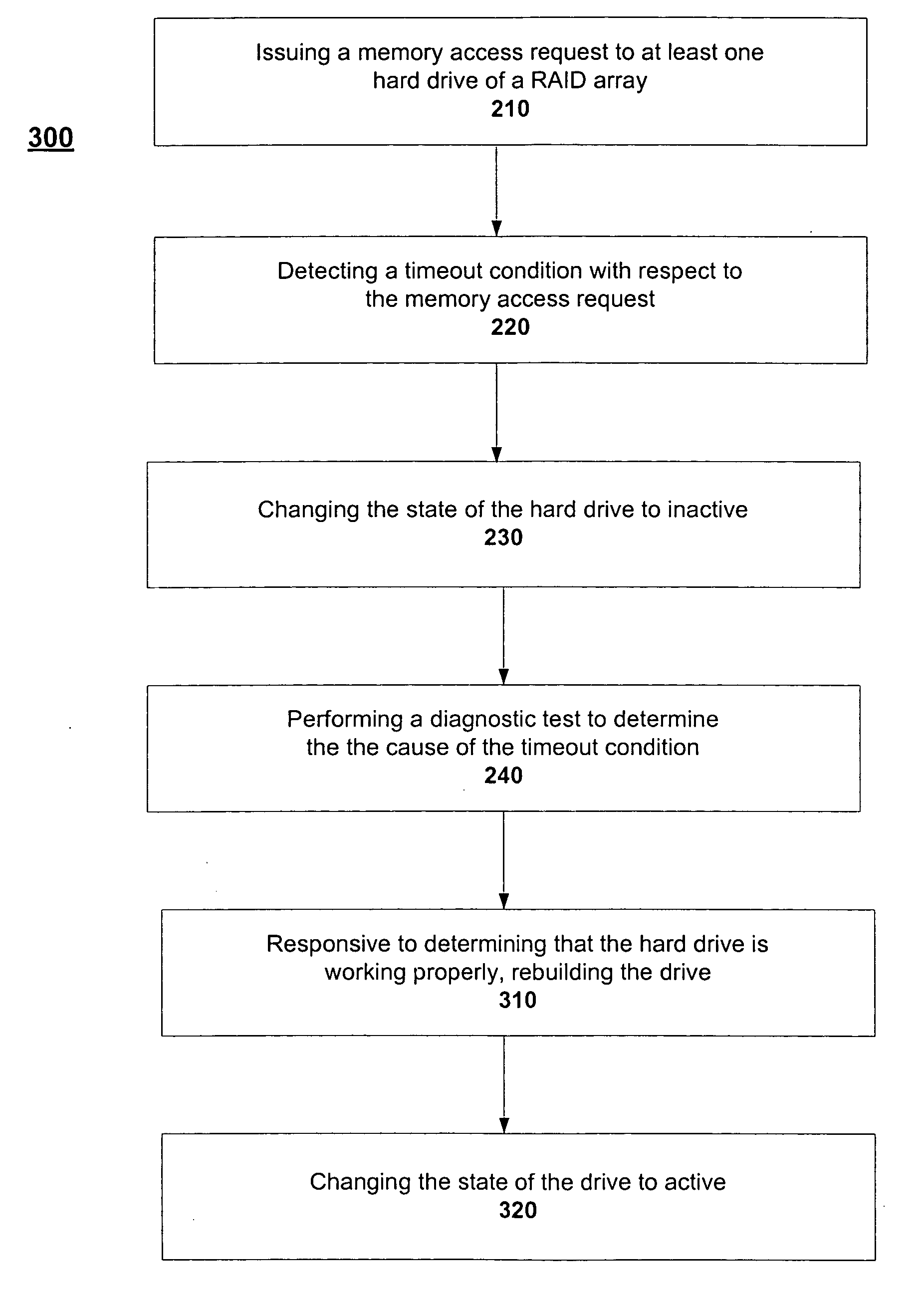
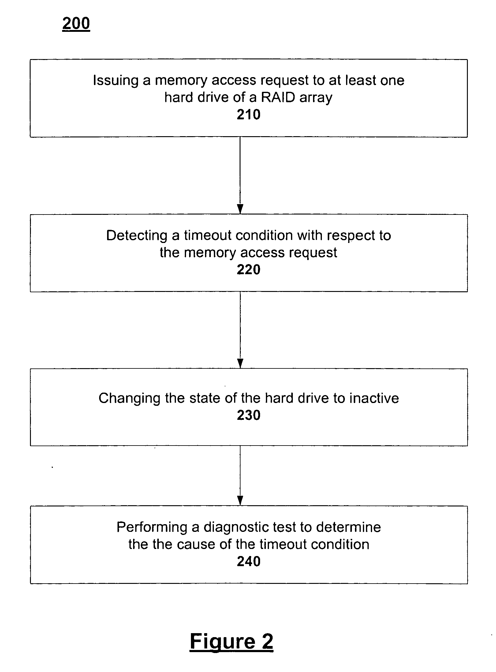
[0020] Systems, apparatuses, and methods for performing diagnostic testing in a RAID are described. In the following description, for purposes of explanation, specific details are set forth in order to provide an understanding of the invention. It will be apparent, however, to one skilled in the art that the invention can be practiced without these details. Furthermore, one skilled in the art will recognize that embodiments of the present invention, described below, may be performed in a variety of mediums, including software, hardware, or firmware, or a combination thereof. Accordingly, the flow charts described below are illustrative of specific embodiments of the invention and are meant to avoid obscuring the invention.

[0021] Reference in the specification to “one embodiment,”“a preferred embodiment” or “an embodiment” means that a particular feature, structure, characteristic, or function described in connection with the embodiment is included in at least one embodiment of the ...


PUM


Abstract

Systems, apparatuses, and methods are described for performing diagnostic testing in a RAID environment in response to a failed memory access request to determine if a hard drive within the RAID failed.

Description

BACKGROUND [0001] A. Technical Field [0002] The present invention relates generally to storage technology, and more particularly, to performing diagnostic testing in a Redundant Array of Independent Disks (RAID) environment. [0003] B. Background of the Invention [0004] As the use of technology in daily life continues to increase, there is an increased amount of digital data that must be stored. Most data is currently stored on hard drives that have large amounts of storage space. As the size of the hard drives and the amount of data increases, technologies for quickly accessing the data become very important. In addition, as the information stored on hard drives becomes more valuable and important to the user, backing up the data in case of a failure, also referred to as fault protection, becomes increasingly important. One technology that is commonly used to improve performance and / or provide fault tolerance is a technology called RAID, which stands for a Redundant Array of Indepen...

Claims


Application Information

Patent Timeline
IPC IPC(8): G06F12/16
CPCG06F11/1092G06F2211/1009G06F11/2221
Inventor HALLYAL, BASAVARAJTHANGARAJ, SENTHIL MURUGANMISHRA, RAGENDRA K.
Owner LSI CORPORATION
Why Eureka
Try Eureka