Cache memory and cache memory control method

a control method and memory technology, applied in the field of cache memory, can solve the problems of large size of storing units, large size of circuits for updating access order data, and large hardware size of hardware, so as to reduce the size of hardware

Inactive Publication Date: 2007-02-01
PANASONIC CORP
View PDF15 Cites 7 Cited by
  • Summary
  • Abstract
  • Description
  • Claims
  • Application Information

AI Technical Summary

Benefits of technology

[0019] As described above, according to the cache memory of the present invention, the size of the hardware can be reduced, while realizing a hit ratio that is equivalent to that of the conventional LRU method.

Problems solved by technology

Therefore, there is a problem that the size of hardware is expanded.
Thus, there is a problem that the size of storing unit (a register or a Random Access Memory (RAM)) for holding access order data and the size of a circuit for updating the access order data are large.

Method used


Image

  • Cache memory and cache memory control method
  • Cache memory and cache memory control method
  • Cache memory and cache memory control method

Examples


first embodiment

[0038]

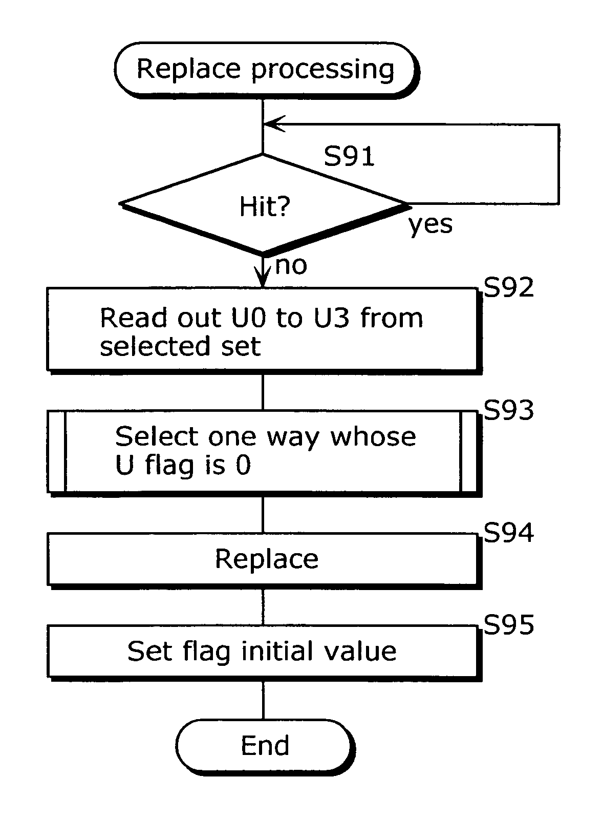
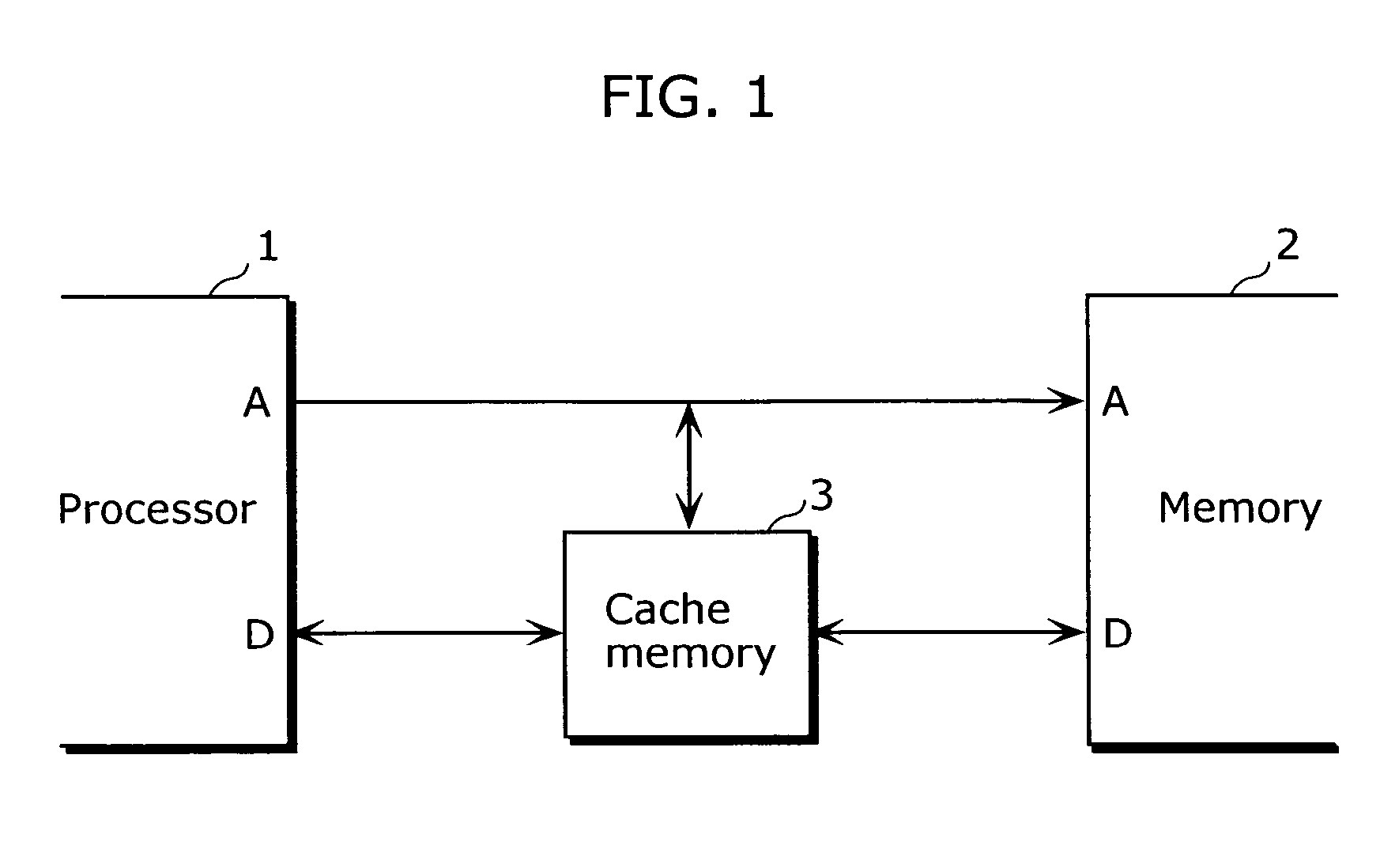
[0039]FIG. 1 is a block diagram showing a rough outline of a structure of a system including a processor 1, a cache memory 3 and a memory 2 according to the first embodiment of the present invention. As shown in the diagram, the cache memory 3 of the present invention is set in a system having the processor 1 and the memory 2, and uses a pseudo LRU method that is obtained by simplifying the LRU method as a replacement algorithm. In the present embodiment, as a pseudo LRU method, there is adopted a method of representing, only by one-bit for each cache entry, data indicating access orders of respective cache entries, and of selecting one entry to be replaced from among cache entries that are represented by a bit value of 0.

[0040]

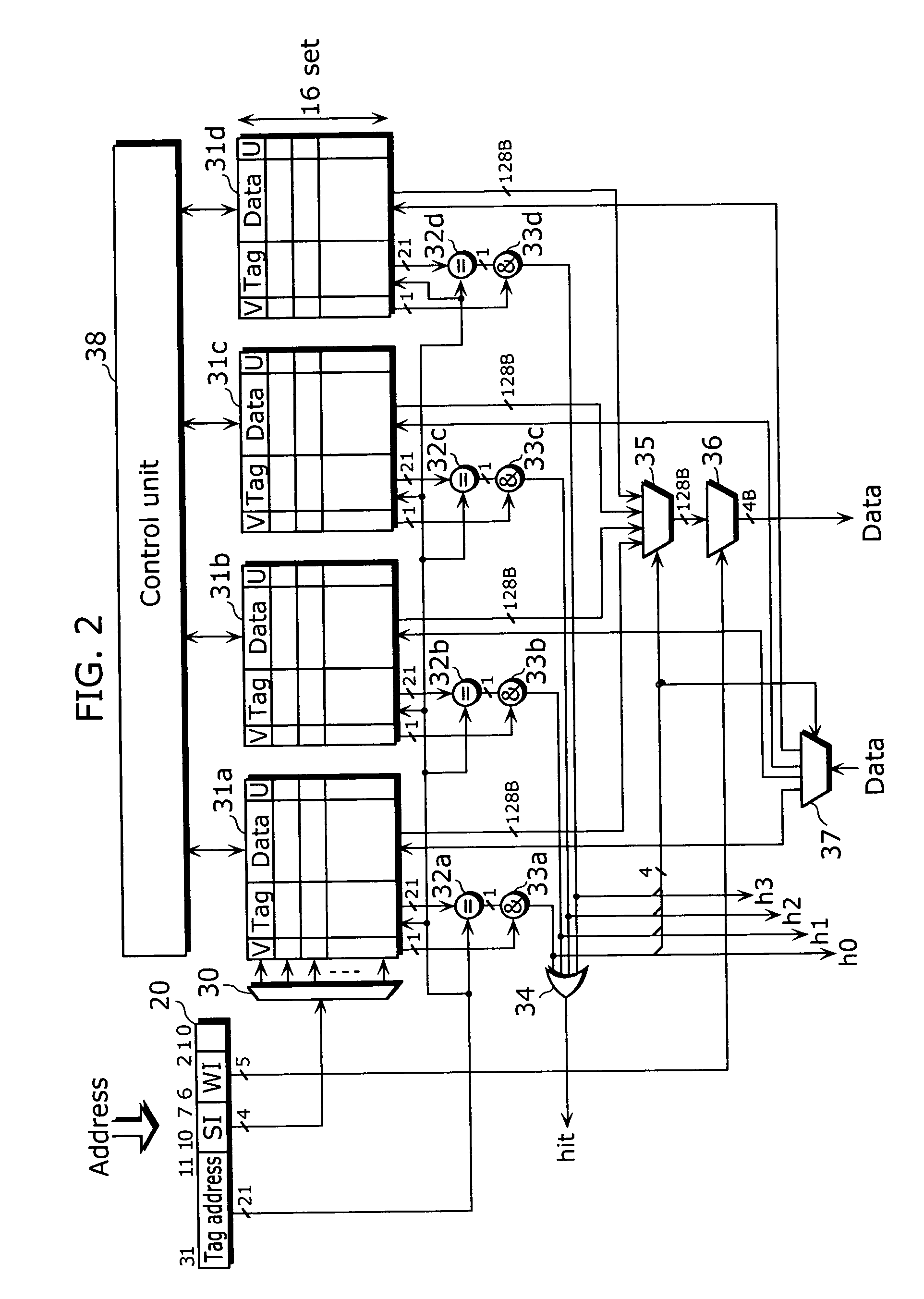
[0041] Hereafter, as a specific example of the cache memory 3, it is explained about a structure in the case where the pseudo LRU is applied to a cache memory of a four-way set-associative method.

[0042]FIG. 2 is a block diagram showing an example of a...

second embodiment

[0093]FIG. 13 is a block diagram showing a structure of a cache memory according to the second embodiment of the present invention. Compared to the structure shown in FIG. 2, the cache memory in the diagram differs in that it has ways 131a to 131d instead of ways 31a to 31d, and a control unit 138 instead of the control unit 38. Hereafter, the different point is mainly explained omitting the explanation about same points.

[0094] The way 131a differs from the way 31a in that a new flag is added to each cache entry.

[0095]FIG. 14 shows a bit structure of one cache entry in the way 131a. As shown in the diagram, it only differs in that a new flag N is added. An initial value of 1 is set to the new flag N immediately after the replacement (or immediately after the fill) and the value is reset to 0 when there the cache entry has been accessed. In other words, the value 1 of the new flag N indicates that the cache entry has not been accessed even once since the replacement (or fill) and i...


PUM


Abstract

A cache memory of the present invention includes: for each cache entry, way 0 to way 3 which hold use flags U indicating whether or not the use flags U have been accessed; and a control unit which: updates, when a cache entry is hit, a use flag U corresponding to the hit cache entry so that the use flag U indicates that the cache entry has been accessed; and reset, in the case where all other use flags in the same set indicates that the cache entries have been accessed herein, the all other use flags so that the use flags indicate that the cache entries have not been accessed; and select a cache entry to be replaced from among the cache entries corresponding to the use flags indicating that the cache entries have not been accessed.

Description

TECHNICAL FIELD [0001] The present invention relates to a cache memory for realizing a high-speed memory access of a processor and a control method thereof. BACKGROUND ART [0002] The Least Recently Used (LRU) method and the First In First Out (FIFO) method are well known as an algorithm for replacing an entry in a conventional cache memory. [0003] The LRU method is a method for determining an entry to be replaced so that the entry is the one whose access order is the oldest among all cache entries. This LRU method is, for example, the most commonly used replacement algorithm that is adopted in the cache memory disclosed in Japanese Laid-Open Patent Application No. 2000-47942. [0004] Incidentally, in order to perform replacement using the algorithm of the LRU method, a storing unit for holding data indicating access orders of respective entries and a complicated circuit for updating the access orders are required. Therefore, there is a problem that the size of hardware is expanded. [...

Claims


Application Information

Patent Timeline
Patent Type & Authority Applications(United States)
IPC IPC(8): G06F12/00G06F12/12
CPCG06F12/127G06F12/124G06F12/12G06F12/08
Inventor TANAKA, TETSUYANAKANISHI, RYUTAKIYOHARA, TOKUZOMORISHITA, HIROYUKICHIKAMURA, KEISHI
Owner PANASONIC CORP
Why Eureka
Try Eureka