Motion vector detection device and motion vector detection method

A motion vector, detection device technology, applied in television, electrical components, digital video signal modification and other directions, can solve problems such as increased hardware

Inactive Publication Date: 2005-06-15
PANASONIC CORP
View PDF0 Cites 4 Cited by
  • Summary
  • Abstract
  • Description
  • Claims
  • Application Information

AI Technical Summary

Problems solved by technology

Therefore, with the expansion of the search range, the amount of hardware will be greatly increased

Method used


Image

  • Motion vector detection device and motion vector detection method
  • Motion vector detection device and motion vector detection method
  • Motion vector detection device and motion vector detection method

Examples


no. 1 approach

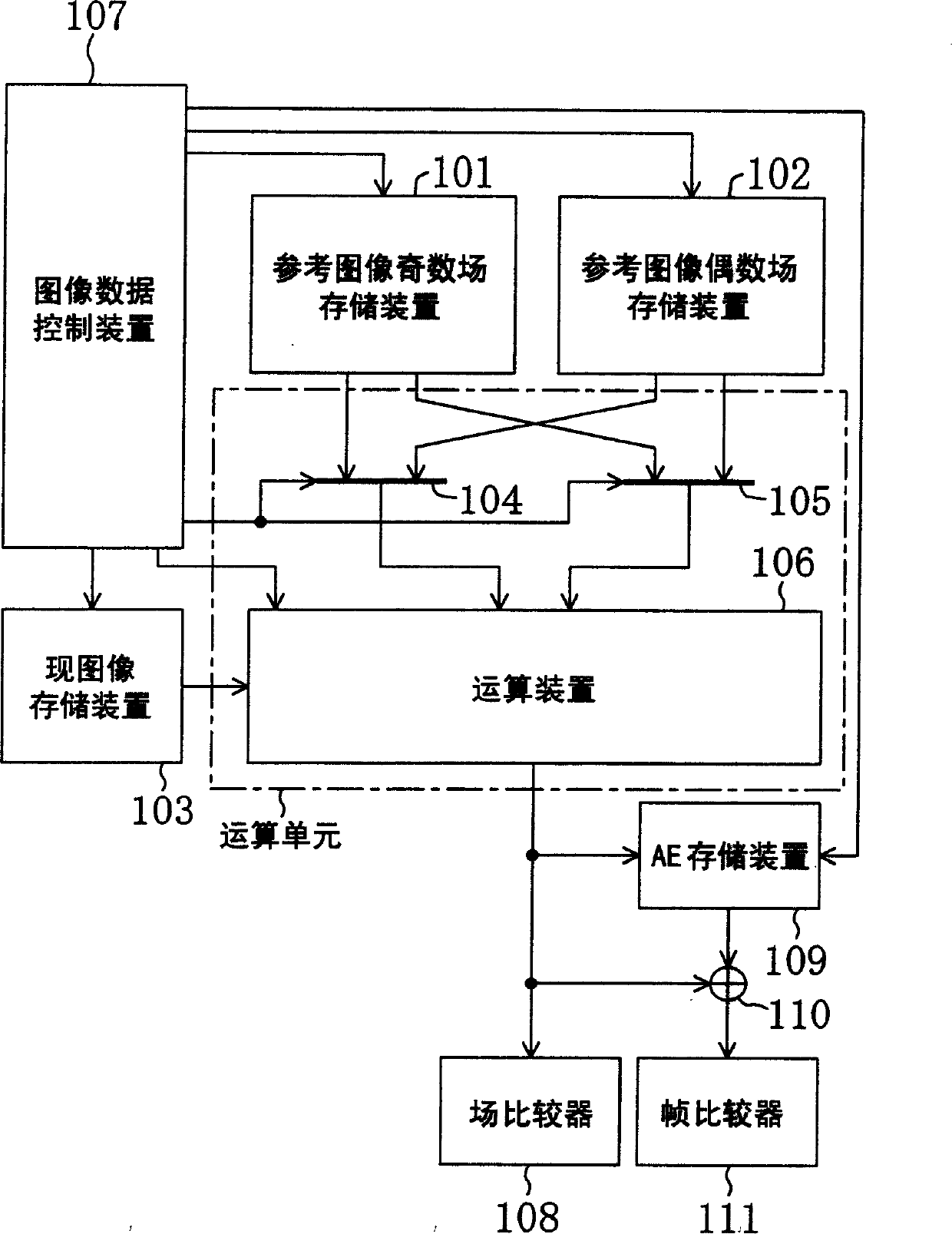
[0075] FIG. 1 is a schematic diagram showing a configuration example of a motion vector detection device 100 according to the first embodiment of the present invention.

[0076] Motion vector detection device 100 shown in Fig. 1 has: reference image odd field storage device 101; Reference image even field storage device 102; Present image storage device 103; Reference image parity selection unit 104 and 105 (included in the computing unit); means 106 (included in the arithmetic unit); image data control means 107; field comparator 108; AE storage means 109; adder 110 and frame comparator 111.

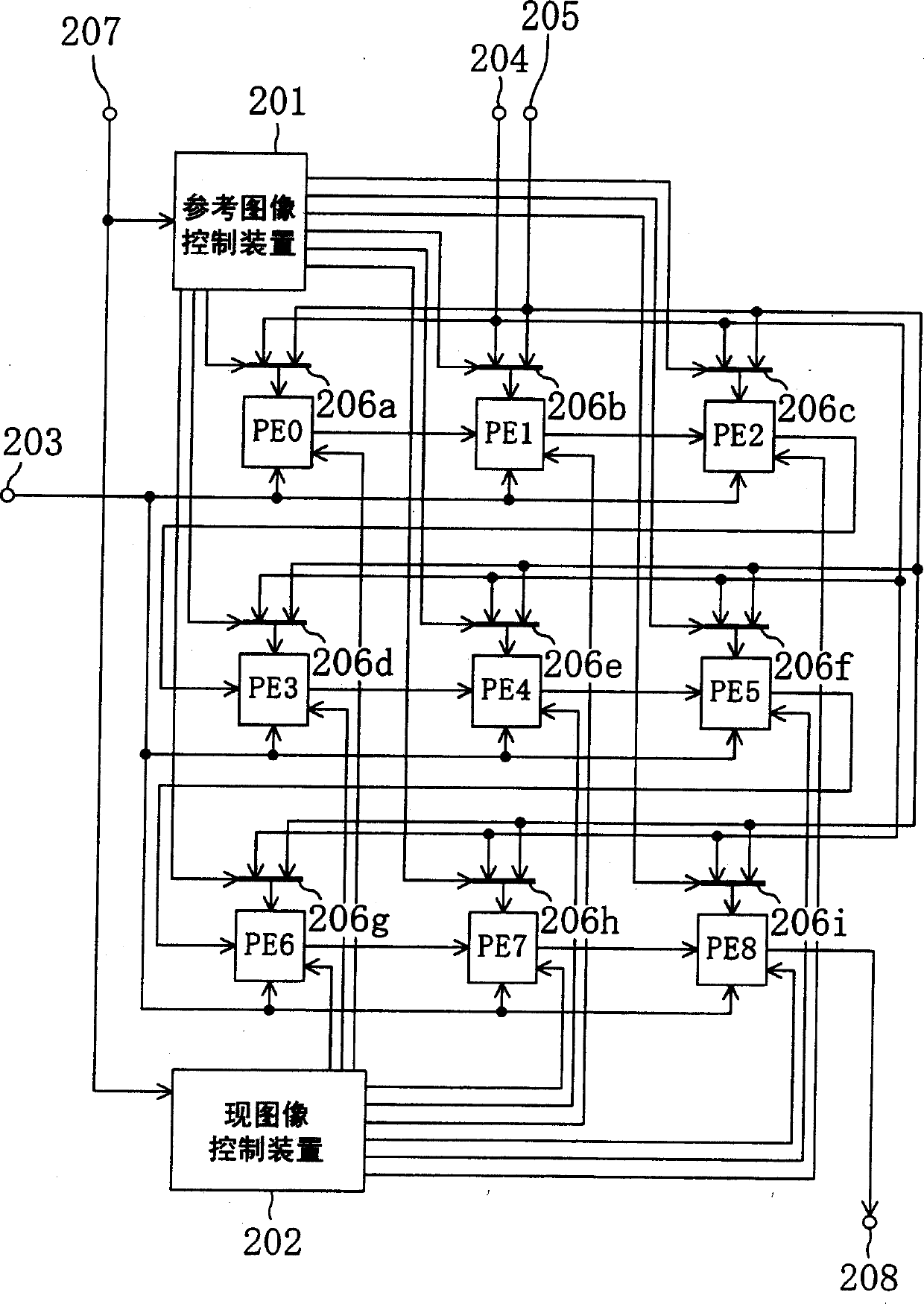
[0077] FIG. 2 is a schematic diagram showing an example of the internal structure of the computing device 106 shown in FIG. 1 .

[0078] The computing device 106 shown in Fig. 2 has: processor components PE0~PE8; reference image control device 201; current image control device 202; current image data input 203; reference image data input 204 and 205; reference image data selection units...

no. 2 approach

[0131] FIG. 9 is a schematic diagram showing a configuration example of a motion vector detection device 200 according to a second embodiment of the present invention.

[0132] Next, as in the first embodiment, the current image frame block and the reference image frame shown in FIG. 4 and FIG. 5 are taken as examples for description.

[0133] The motion vector detection device 200 shown in FIG. 9 has: a current image storage device 112; an image data control device 113;

[0134] FIG. 10 is a schematic diagram showing an example of the internal structure of the computing device 114 shown in FIG. 9 .

[0135] The arithmetic unit 114 shown in FIG. 10 has: processor units PE0-PE8 equal in number to the number of pixels of the candidate block for one field; a current image control unit 209; Other constituent elements are the same as those of the first embodiment.

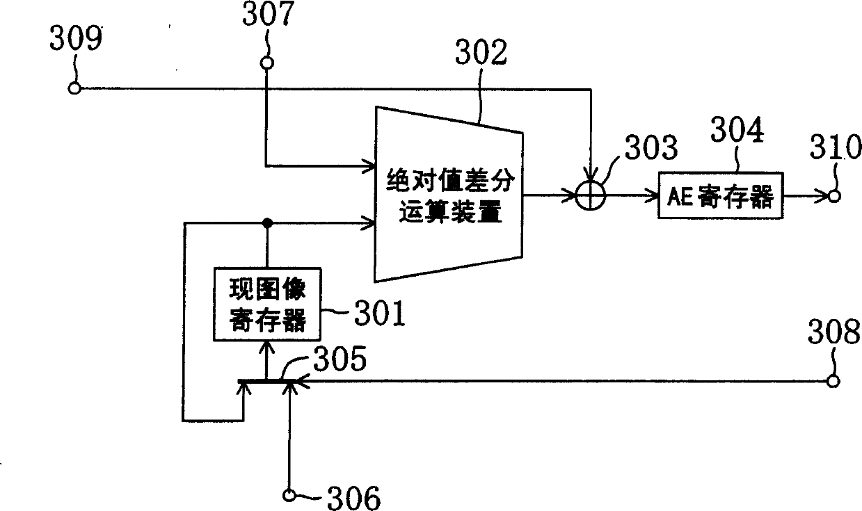
[0136] FIG. 11 is a schematic diagram showing an example of the internal structure of each of the processor element...

no. 3 approach

[0169] FIG. 12 is a schematic diagram showing a configuration example of a motion vector detection device 300 according to a third embodiment of the present invention.

[0170] Next, as in the first embodiment, the current image frame block and the reference image frame shown in FIG. 4 and FIG. 5 are taken as examples for description.

[0171] Motion vector detection device 300 shown in FIG. 12 has: image data control device 115; computing device 116 (corresponding to computing unit); register 117 capable of storing AE (prediction error for a candidate vector) of one search point. Other constituent elements are the same as those of the first embodiment.

[0172] FIG. 13 is a diagram showing an example of the internal structure of the arithmetic unit 116 shown in FIG. 12, which has processor elements PE equal in number to the number of pixels of one field of the candidate block. Each of the processor components PE0 to PE8 is the same as that shown in FIG. 11 used in the second...


PUM


Abstract

The operation unit sequentially calculates the prediction error for each candidate vector based on the pixel data of the odd or even field and the pixel data of the odd or even field of the current image block, and the field comparator detects that the minimum prediction error is obtained among the calculated prediction errors The field motion vector of . The AE storage means stores a plurality of prediction errors calculated by the arithmetic unit on one of the prescribed combinations. The adder adds the prediction error calculated by the arithmetic unit to a corresponding one of the plurality of prediction errors stored in the AE storage device to calculate the prediction error in units of frames. Then, the frame comparator detects a frame motion vector that obtains the smallest prediction error among the calculated prediction errors in units of frames.

Description

technical field [0001] The present invention relates to a motion vector detection device and a motion vector detection method for obtaining a motion vector in a moving image encoding device. Background technique [0002] As a method for realizing image compression of a moving image, there is a method of reducing redundancy by using information (motion vector) indicating where a certain part in the previous screen has moved on the current screen. [0003] A block matching method is known as a technique for extracting the motion vector. The block matching method is to firstly divide the encoding target image frame (hereinafter referred to as the current image frame) into a plurality of blocks (the current image block), and from the plurality of blocks (referred to as the reference image frame in the past) or the future frame (hereinafter referred to as the reference image frame) The reference image block with the highest correlation with the current image block is extracted f...

Claims


Application Information

Patent Timeline
Patent Type & Authority Applications(China)
IPC IPC(8): H04N7/26
CPCH04N19/105H04N19/112H04N19/16H04N19/43H04N19/51
Inventor 相原祐一郎大谷昭彦渡部彰启
Owner PANASONIC CORP
Why Eureka
Try Eureka