Roller screw

a roller screw and roller technology, applied in the field of roller screw, can solve the problems of defective and inconvenient, the load to be applied to the roller screw cannot be made large, and the roller screw skew can be surely prevented, and achieve the effect of smooth movement, smooth movement and smooth movemen

Inactive Publication Date: 2007-02-08
THK CO LTD
View PDF6 Cites 20 Cited by
  • Summary
  • Abstract
  • Description
  • Claims
  • Application Information

AI Technical Summary

Benefits of technology

[0017] According to the invention of claim 1, since the concave portions of the spacer contact the roller to thereby keep the predetermined attitude of the roller, the roller can smoothly circulate without causing any skew.
[0018] According to the invention of claim 2, the skew of the roller can be surely prevented.
[0019] According to the invention of claim 3, the roller can smoothly circulate without causing any skew with respect to either one of spiral track of the loaded roller rolling passage and linear track in the return member. Although details will be described hereinafter, when the concave portions on both ends of the spacer are formed so that the axis of the roller rolling in the spiral loaded roller rolling passage inclines toward the center of the screw shaft in a state viewed from the axial direction of the screw shaft, the roller moves in the linear track, for example, of the ret

Problems solved by technology

However, in such arrangement, the balls contact substantially at point contact to the ball rolling groove of the screw shaft surrounding the balls and the loaded ball rol

Method used


Image

  • Roller screw
  • Roller screw
  • Roller screw

Examples


Embodiment Construction

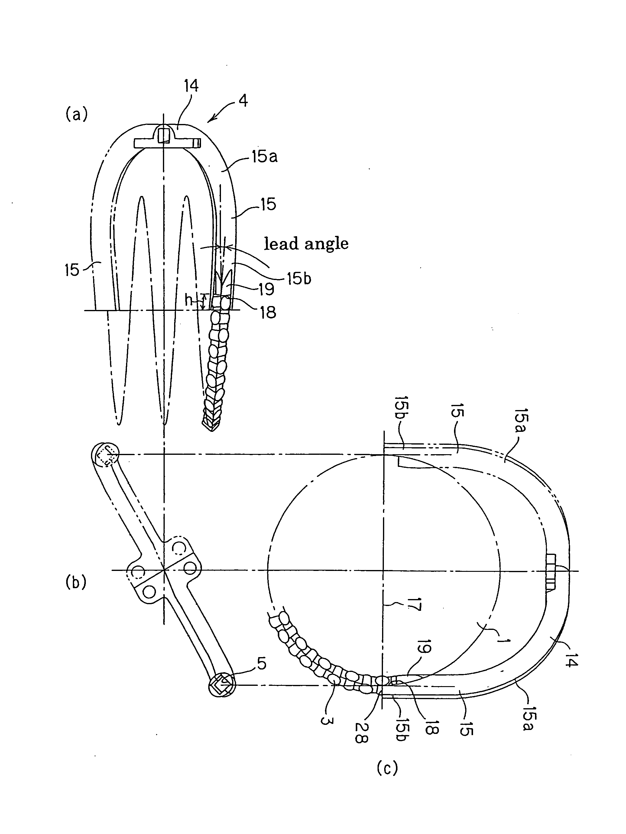
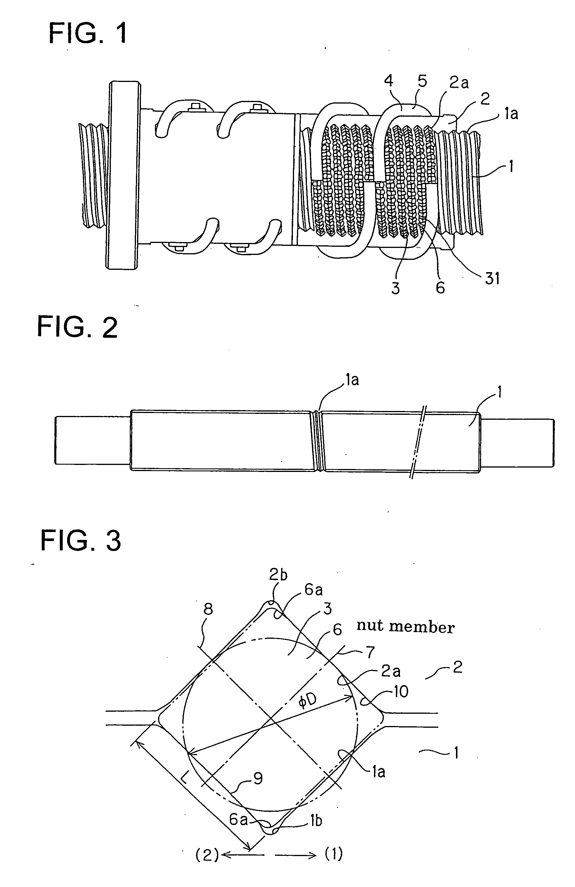
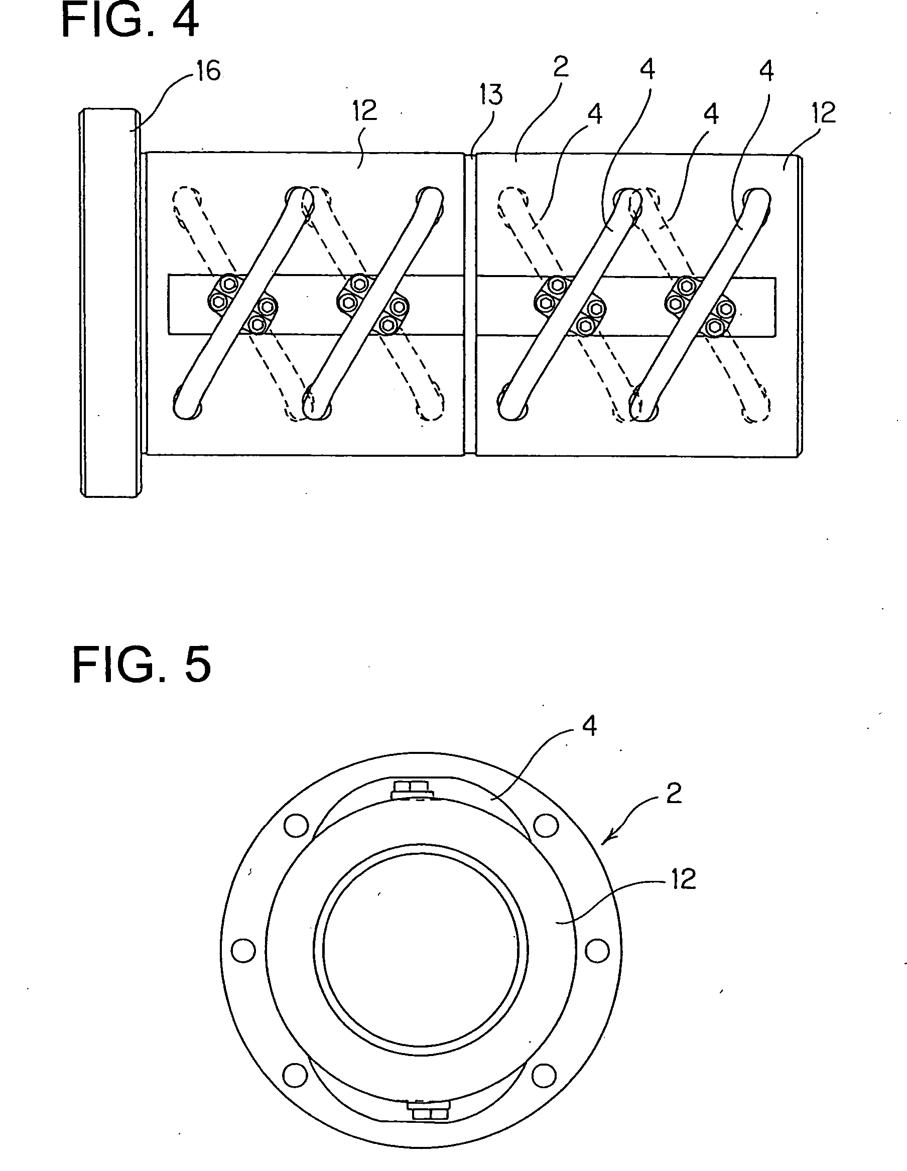
[0042]FIG. 1 shows a roller screw according to one embodiment of the present invention. The roller screw includes a screw shaft 1 formed, in its outer peripheral surface, with a roller rolling groove 1a in form of spiral and a nut member 2 formed, in its inner peripheral surface, with a loaded roller rolling groove, in form of spiral, and assembled with the screw shaft 1 to be relatively rotatable. The nut member 2 is provided with a return pipe 4 as a circulation member connecting one and the other ends of a loaded roller rolling groove 3 between the roller rolling groove la of the screw shaft 1 and the loaded roller rolling groove 2a of the nut member 2. Inside the return pipe, there is formed a roller return passage 5, having a rectangular section such as square shape in this embodiment, along the axial direction of the return pipe. A number of rollers 6 are accommodated and arranged in the loaded roller rolling passage 3 formed by the roller rolling groove 1a of the screw shaft ...


PUM


Abstract

A roller screw includes: a screw shaft 1 having an outer peripheral surface in which a spiral roller rolling groove 1a is formed; a nut member 2 having an inner peripheral surface in which a spiral loaded roller rolling groove 2a is formed so as to oppose to the roller rolling groove 1a; a return pipe 4 connecting one and another ends of a loaded roller rolling groove 2a of the nut member 2; and a plurality of rollers 6 disposed in the loaded roller rolling passage 3 and the return pipe 4. A spacer 31 is disposed between a pair of adjacent rollers 6, 6 so as to prevent the paired rollers 6, 6 from contacting each other. According to such roller screw, the rollers can be smoothly circulated without causing any skew.

Description

TECHNICAL FIELD [0001] The present invention relates to a roller screw in which rollers are disposed to be capable of carrying out a rolling motion between a screw shaft and a nut member. BACKGROUND TECHNOLOGY [0002] There is known a ball screw in which balls are disposed to be movable between the screw shaft and the nut member. The balls are disposed between a spiral ball rolling groove formed to an outer peripheral surface of the screw shaft and a spiral loaded ball rolling groove formed to an inner peripheral surface of the nut member. When the screw shaft is rotated relative to the nut member, a number of balls roll on the ball rolling groove of the screw shaft and the loaded ball rolling groove of the nut member. The ball rolls to one end of the loaded ball rolling groove of the nut member is scooped up by a ball return member connecting one and the other ends of the loaded ball rolling groove and then returns to the original position in the loaded ball rolling groove, and thus...

Claims


Application Information

Patent Timeline
IPC IPC(8): F16H25/22
CPCF16H25/2214F16H25/2238F16H25/2247Y10T74/19777F16C33/3706Y10T74/19749F16H2025/2271F16H25/22
Inventor TERAMACHI, AKIHIROMICHIOKA, HIDEKAZUNIWA, HIROSHINISHIMURA, KENTARO
Owner THK CO LTD
Why Eureka
Try Eureka