
Condiment Dispensing System

a dispenser and liquid technology, applied in the field of dispensers, can solve the problems of reducing efficiency, reducing operational speed, reducing efficiency, etc., and achieve the effects of minimizing waste and potentially damaging the package during use, reducing the time required to insert the bag, and increasing the accuracy of insertion

Inactive Publication Date: 2007-02-08
CLEAR LAM PACKAGING
View PDF9 Cites 31 Cited by
  • Summary
  • Abstract
  • Description
  • Claims
  • Application Information

AI Technical Summary

Benefits of technology

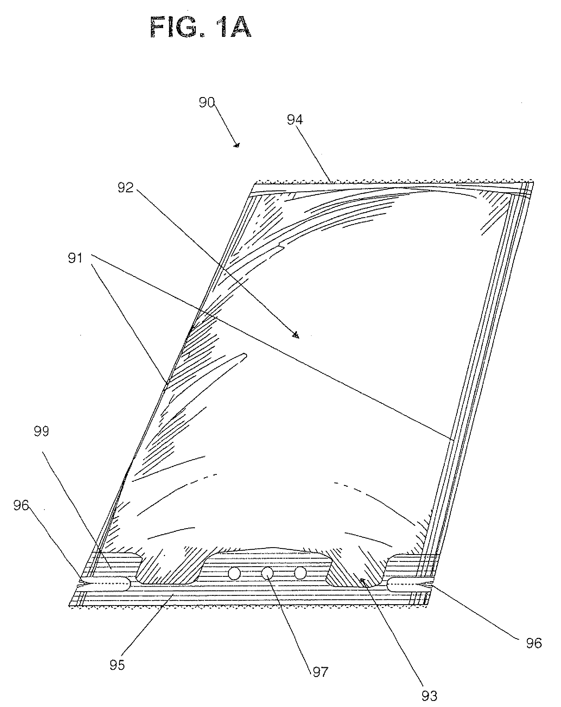
[0010] However, accurately fitting a flexible bag into any of these dispensers has been problematic. An appropriate fit of the bag within a dispensing device is important to ensure correct insertion, as well as minimizing waste and potentially damaging the package during use. It is further desirable to minimize the time required to insert the bag, while simultaneously increasing the accuracy of the insertion. It is also desirable to provide a bag that minimizes clean up and disposal costs. It is further desirable that the bag can be manufactured on a variety of packaging machines with the insertion of customized seal jaws to create spouts, locator pins and tear notches.

Problems solved by technology

While tin cans offer good shelf life performance, tin cans contribute to waste of product that clings to the side of cans.
Further, tin cans are heavy to ship, store, and are heavy and voluminous for disposal.
Additionally, tin cans require can openers to open - retrieving the opener reduces operational speed, and the opener may be difficult to locate, further reducing efficiency.
Opening tin cans may also result in sharp edges that may tear garbage bags and pose a laceration risk.
However, gallon jugs contribute to waste in the same fashion as tin cans, and share many of the negative attributes of tin cans.
Caulk cartridge type cans leave less product in the canister, but require priming of each can and generate significant wasted product.
For example, a 25-ounce cartridge delivering a one-ounce payload necessarily wastes 4% of the product due to priming.
Devices that use gravity actuated rollers or gears are complicated to manufacture and may involve manipulating the rollers in non-intuitive ways.
Other devices that utilize more complex means for releasing condiment from the bags require that the bags incorporate specially designed fittings, including tubes and couplings, which increase the cost and complexity of the packaging and add to product waste during cleanup.
Yet other devices use motorized pumps that require electricity and possibly pressurized gases to operate, which adds to the cost and size of the dispensers, increasing manufacturing costs and adding complexity during cleaning.
Further, pumps may result in undesired splatter, which both wastes product, as well as work effort to clean the splatter.
If a pump in the front of the store splatters, customers may become unhappy.
Motorized devices often require long tubes that contribute to waste of the condiment and complicate clean up.
Furthermore, existing types of dispensers have a single outlet for the condiment, which reduces efficiency at workstations where multiple outlets can be accommodated.
Additionally, tubes reduce the range of movement and freedom of motion of the applicator device.
Additionally, devices using pressurized gas rely on the gas, and in event of gas malfunction, or lack of gas supply, the device is non-functional.
Other devices utilize fitments that require significant expense, and contribute to waste if the fitment is improperly fitted.
However, accurately fitting a flexible bag into any of these dispensers has been problematic.

Method used


Image

  • Condiment Dispensing System
  • Condiment Dispensing System
  • Condiment Dispensing System

Examples


Embodiment Construction

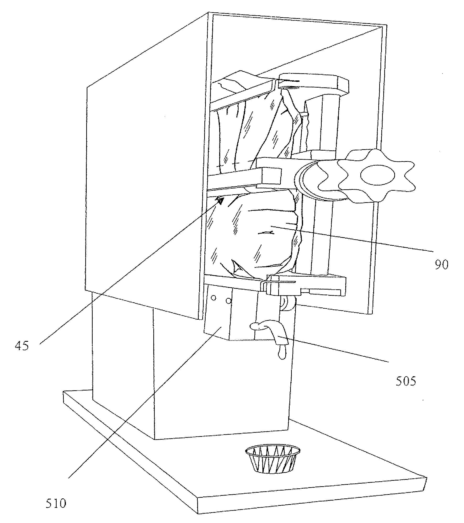
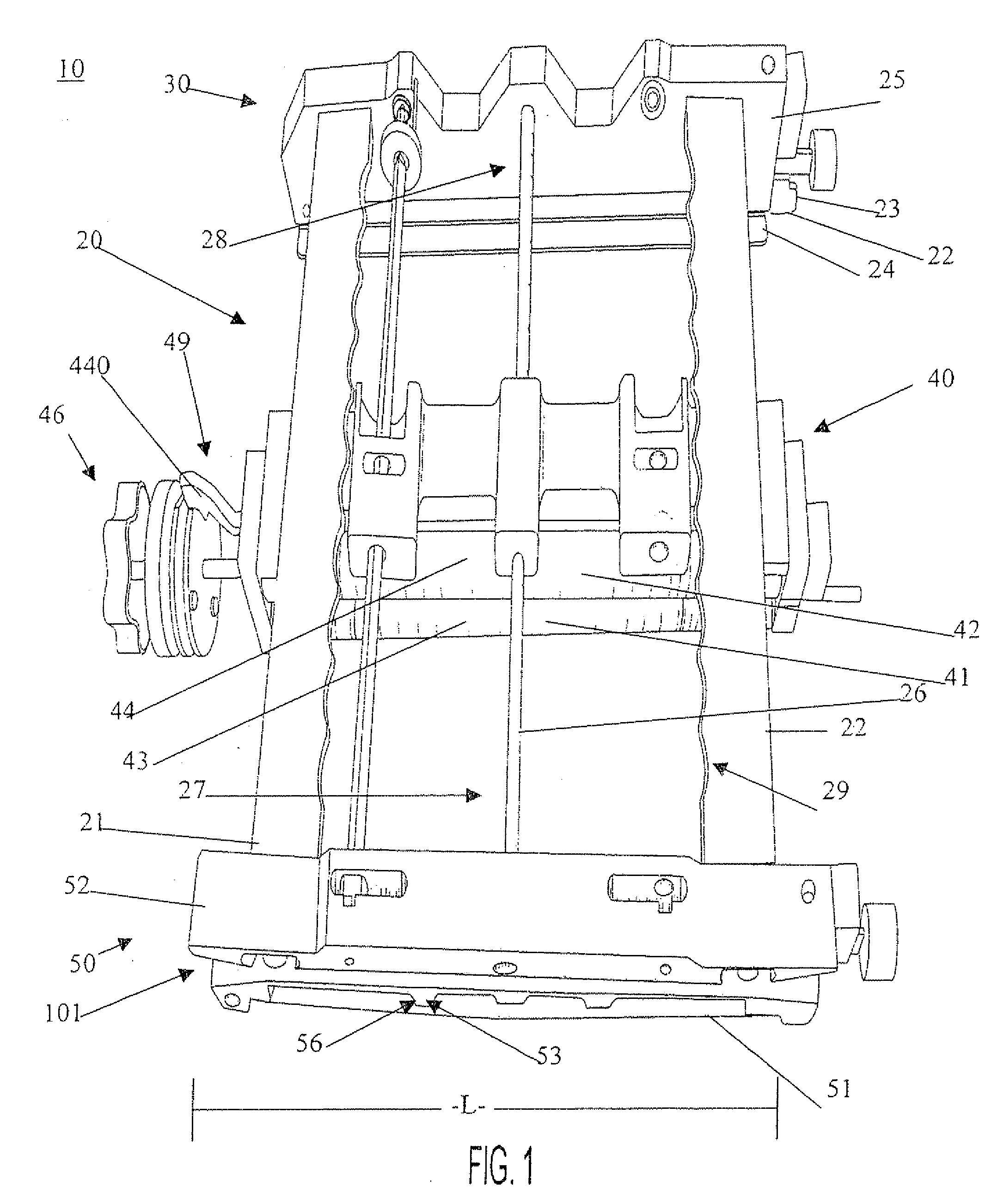
[0047]FIG. 1 illustrates a system 10 in accordance with one embodiment of the invention. System 10 includes a frame 20, top clip 30, roller frame 40, and valve assembly 50. System 10 further includes housing 5 (see FIG. 6) and dispenser 310 (see FIGS. 3A and 3B). In one embodiment, flexible bag 90 is retained and supported, at least in part, by top clip 30 and held within roller assembly 40.

[0048] Housing 5 is operable to support frame 20. In one embodiment, housing 5 is a freestanding unit, configurable to rest upon, for example, a tabletop. In another embodiment, housing 5 is configured as a wall-mounted unit. In one embodiment, frame 20 includes a male adaptor configured to mate with a female adaptor in housing 5 for a sliding engagement between frame 20 and housing 5. In one embodiment, frame 20 includes a female adaptor configured to mate with a male adaptor in housing 5 for a sliding engagement between frame 20 and housing 5. Embodiments with a female adaptor on the frame 20 ...


PUM


Abstract

A system for dispensing product includes a track support, the track support comprising a one-piece frame and a roller assembly slidably engaged with the one-piece frame, the roller assembly including a first lobed roller and a second lobed roller. The system further includes a valve assembly attached to a base portion of the one-piece frame, wherein a flexible product filled bag is retainable between the roller assembly and wherein the roller assembly translates down the track support to force the product toward the valve assembly.

Description

RELATED APPLICATIONS [0001] This application claims priority to U.S. Provisional Patent Applications 60 / 718,797 filed Sep. 20, 2005. This application is a continuation-in-part of U.S. application Ser. No. 11 / 031,243 filed Jan. 6, 2005 which claims the benefit of U.S. Provisional Patent Applications 60 / 534,581 filed Jan. 6, 2004. This application is also a continuation-in-part of U.S. application Ser. No. 11 / 031,645 filed Jan. 7, 2005 which claims the benefit of U.S. Provisional Patent Application, 60 / 534,644 filed Jan. 7, 2004, and 60 / 545,122 filed Feb. 17, 2004. The entirety of each application is hereby incorporated by reference.FIELD OF THE INVENTION [0002] This invention generally relates to the art of dispensers and, particularly, to a condiment dispenser. BACKGROUND OF THE INVENTION [0003] The ability to dispense a controlled quantity of a condiment, such as ketchup, mustard, relish, mayonnaise, salad dressings, hot wings sauce, spaghetti sauce, tartar sauce or other sauces, i...

Claims


Application Information

Patent Timeline
Patent Type & Authority Applications(United States)
IPC IPC(8): B65D35/28
CPCA47G19/183B67D1/0001G01F11/32G01F11/021B67D2001/0812
Inventor SANFILIPPO, JAMES J.SANFILIPPO, JOHN E.SORIA, JAVIERWONG, KOON
Owner CLEAR LAM PACKAGING
Learn More