Gantry system for a particle therapy facility

Inactive Publication Date: 2007-02-08
SIEMENS AG
View PDF6 Cites 100 Cited by
  • Summary
  • Abstract
  • Description
  • Claims
  • Application Information

AI Technical Summary

Benefits of technology

[0006] An object of the invention is to provide a gantry system which enables accurate radiation ther

Problems solved by technology

The problem thus arises, in particular, that the gantry system, which has been dimensioned with a view to adequate rigidity, nevertheless, depending on the angle of rotation, undergoes different displacements or distortions or de

Method used


Image

  • Gantry system for a particle therapy facility
  • Gantry system for a particle therapy facility
  • Gantry system for a particle therapy facility

Examples


Example

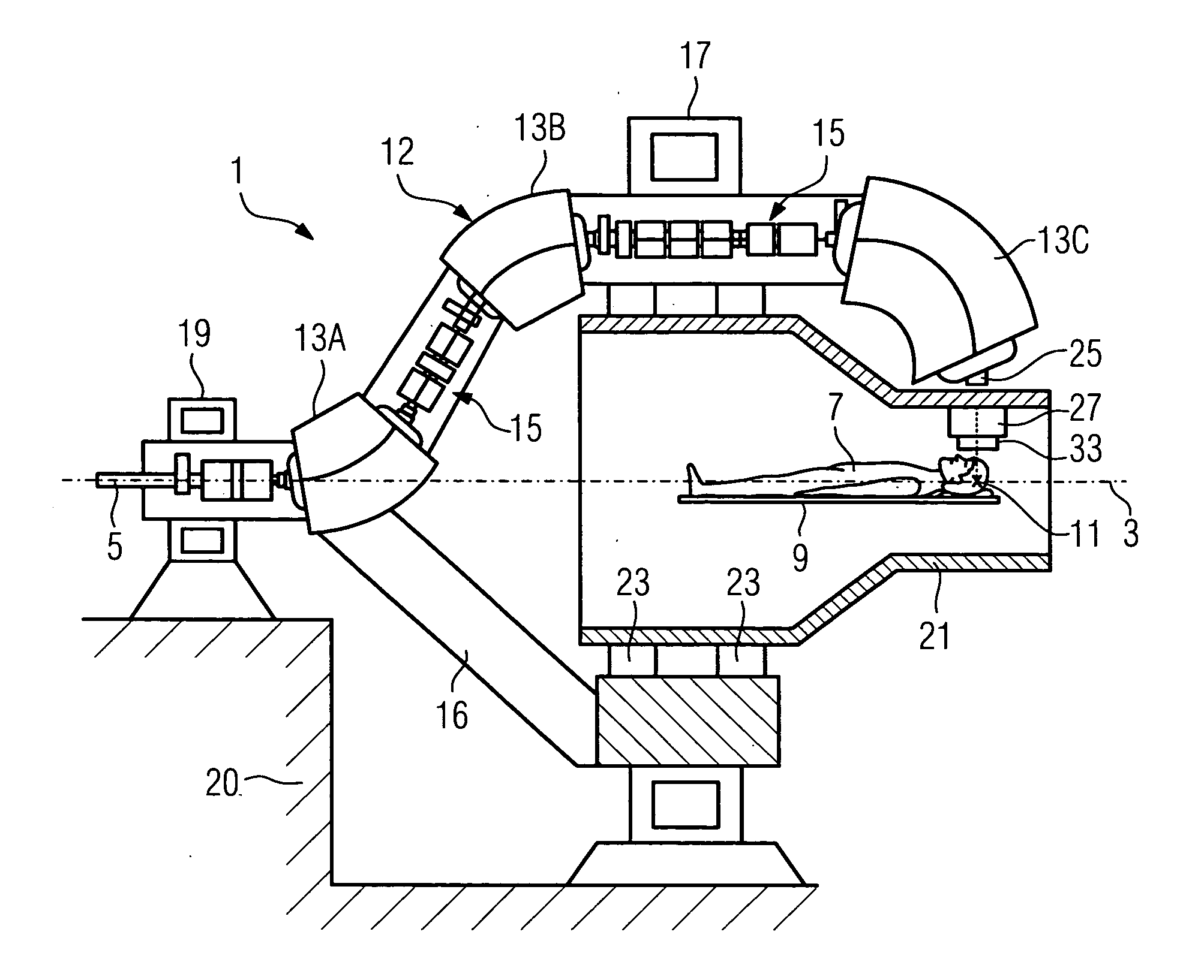
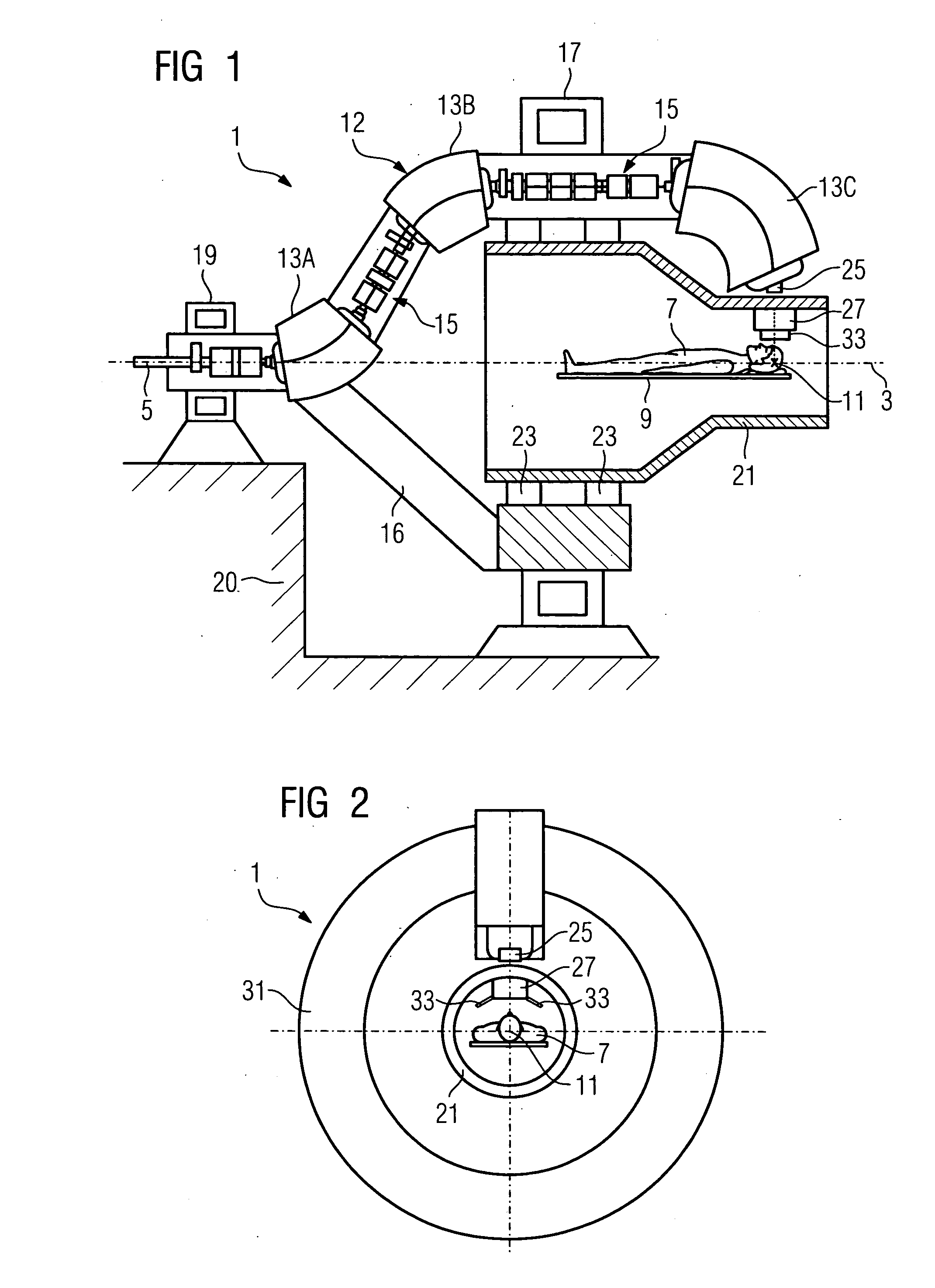
[0023]FIG. 1 shows a gantry system 1 in a vertical sectional drawing along an axis of rotation 3. The object of the gantry system 1 is to be able to guide a particle beam 5 such that a patient 7 having tissue that is to be irradiated, for example having a brain tumor, can undergo radiation therapy from any direction of incidence. For this purpose, the patient 7 is positioned, for example on a patient bed 9, with the tissue to be irradiated in an isocenter 11 of the gantry system 1. The isocenter 11 preferably lies on the axis of rotation 3. The direction of incidence can be at any angle to the axis of rotation 3. For illustrative purposes, an angle of 90° was selected in FIG. 1. When the gantry system 1 rotates, the direction of incidence rotates about the axis of rotation 3.

[0024] In the exemplary embodiment shown in FIG. 1, the particle beam is guided by the beam guidance gantry 12 from the beam entry into the gantry system 1 to the patient 7. The particle beam 5 enters the gantr...


PUM


Abstract

The invention relates to a gantry system for a particle therapy facility, having a beam guidance gantry which has elements for beam guidance, and having a measurement gantry which has a device for beam monitoring. The measurement gantry and beam guidance gantry are thus of a mutually independent design and are, in particular, arranged in a mutually concentric manner. A gantry system of this kind is inter alia less susceptible to mechanical deviations during rotation of the beam guidance gantry.

Description

CROSS REFERENCE TO RELATED APPLICATIONS [0001] The present application claims the benefit of the provisional patent application filed on Aug. 5, 2005, and assigned application No. 60 / 705,824. The present application also claims priority of German application No. 10 2005 037 018.7 filed on Aug. 5, 2005. Both of the applications are incorporated by reference herein in their entirety.FIELD OF THE INVENTION [0002] The invention relates to a gantry system for a particle therapy facility, having a beam guidance gantry which has elements for beam guidance. BACKGROUND OF THE INVENTION [0003] In particle therapy, gantry systems are used to irradiate patients from different directions with particles, that is to say protons, carbon ions or oxygen ions, for example. For this purpose the gantry comprises a plurality of deflection magnets which rotate about the axis of rotation of the gantry system. Beam monitoring elements are usually arranged at a beam exit. These elements supply, for example, ...

Claims


Application Information

Patent Timeline
IPC IPC(8): G21G4/00
CPCA61N5/10A61N5/1048A61N2005/1087A61N2005/105A61N5/1081
Inventor HERMANN, KLAUSKAISER, WERNERSOMMER, ANDRESZEUNER, TORSTEN
Owner SIEMENS AG
Why Eureka
Try Eureka