
Apparatus and method for capturing a scene using staggered triggering of dense camera arrays

a technology of camera array and camera array, applied in the field of apparatus and methods for capturing scenes with dense camera array, can solve the problems of limiting the highest achievable system frame rate, distortion cannot be corrected, rolling shutter distortion, etc., to achieve the effect of improving sampling accuracy, reducing computational load, and increasing temporal resolution

Active Publication Date: 2007-02-08
THE BOARD OF TRUSTEES OF THE LELAND STANFORD JUNIOR UNIV
View PDF22 Cites 86 Cited by
  • Summary
  • Abstract
  • Description
  • Claims
  • Application Information

AI Technical Summary

Benefits of technology

[0015] In view of the above, it is an object of the present invention to provide an apparatus and method for deliberately and precisely controlling camera arrays, and in particular the triggering of frame capture in such arrays in a manner that is well-suited for processing. Specifically, it is an object of the invention to control the timing of frame capture in a manner that permits spatio-temporal interpolation and processing of new visual outputs with minimal computational load.
[0016] It is a further object of the invention to ensure that the apparatus and method provide for better sampling including spatio-temporal sample distribution, increased temporal resolution and ability to capture quicker or more complex motion events in the scene, and more particularly in a three-dimensional region of interest in the scene.
[0017] It is still another object of the invention to ensure that the apparatus is low cost, scalable to large arrays of video cameras and easy to implement.
[0018] These and other advantages and objects of the invention will become apparent from the ensuing description.
[0019] The invention concerns an apparatus and a method for video capture of a three-dimensional region of interest in a scene using an array of video cameras. The video cameras of the array are positioned for viewing the three-dimensional region of interest in the scene. Each camera has a viewpoint, such that the region of interest is seen from a set of viewpoints corresponding to the cameras making up the array. A triggering mechanism is provided for staggering the capture of a set of frames by the video cameras of the array. The apparatus has a processing unit for combining and operating on the set of frames captured by the array of cameras

Problems solved by technology

This system does not scale to a large number of cameras and thus limits the highest achievable system frame rate.
In addition, due to small number of cameras it suffers from rolling shutter distortion when capturing fast moving objects in the scene.
This distortion cannot be corrected without having visible seams in the image.
As a result, they cannot guarantee a constant frame rate for the final sequence.
More importantly, their formulation relies on overlapping exposure times, resulting in blurry images.
This operation is known to be ill-conditioned and is only marginally successful while being computationally intensive.
These do not, however, scale well to large numbers of cameras.
Still other prior art methods use still cameras with a configurable delay between triggers.
Because of the delay between cameras the trigger must run serially through the entire array of cameras and as it does so, each delay adds some timing uncertainty in addition to the propagation time for the signal.
More importantly, this system works only for still cameras, since video cameras usually run at constant frame rates.
The Manex system cannot guarantee that, especially with large numbers of cameras and arbitrary delays.
More generally, these methods and systems are not designed to allow the user to derive arbitrary space-time trajectories after filming just once.
However, Shum provides no teaching on temporal sampling for image-based rendering.
For static scenes, this is still a challenging vision problem that requires sophisticated computational methods that incorporate data from all or many images.

Method used


Image

  • Apparatus and method for capturing a scene using staggered triggering of dense camera arrays
  • Apparatus and method for capturing a scene using staggered triggering of dense camera arrays
  • Apparatus and method for capturing a scene using staggered triggering of dense camera arrays

Examples


Embodiment Construction

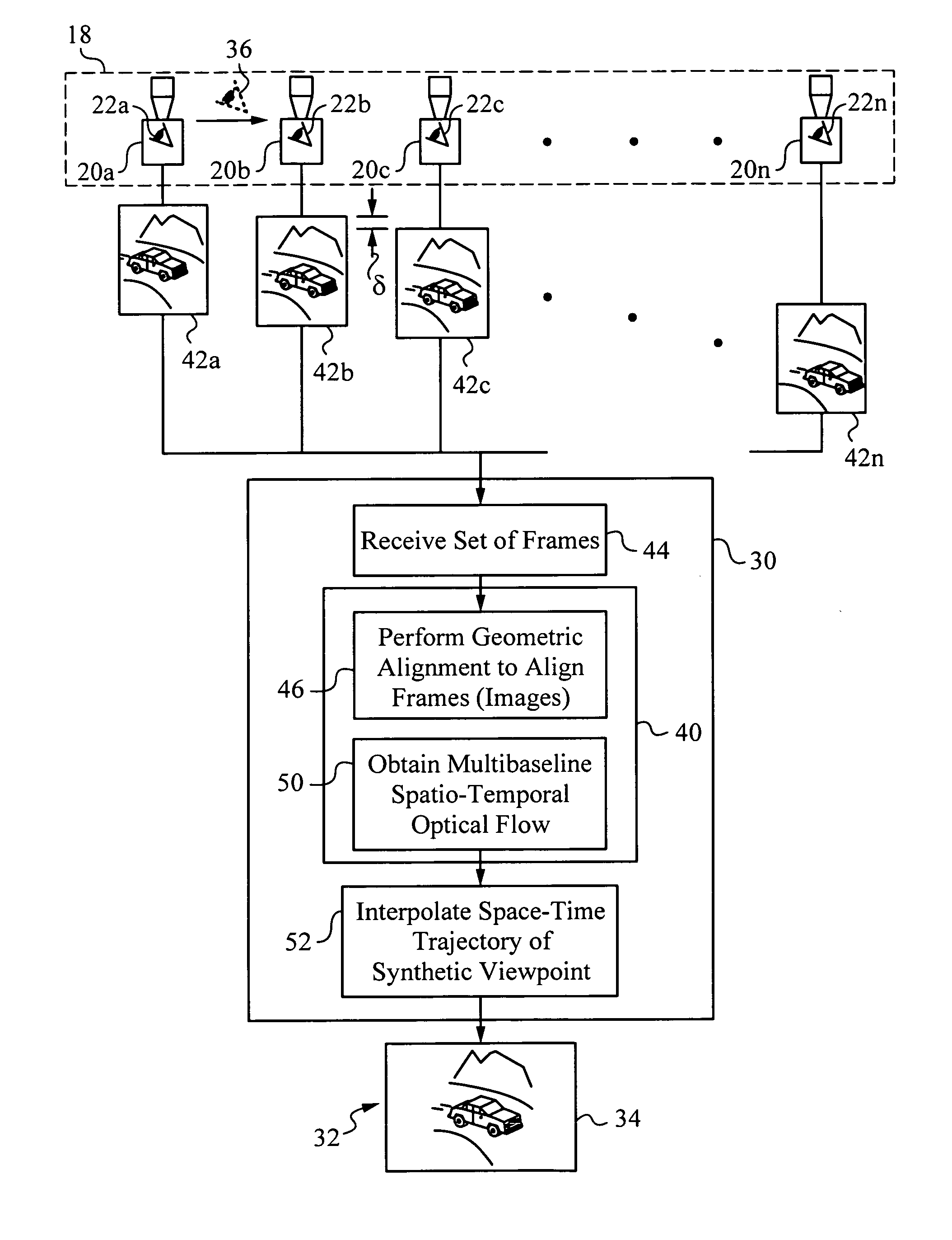
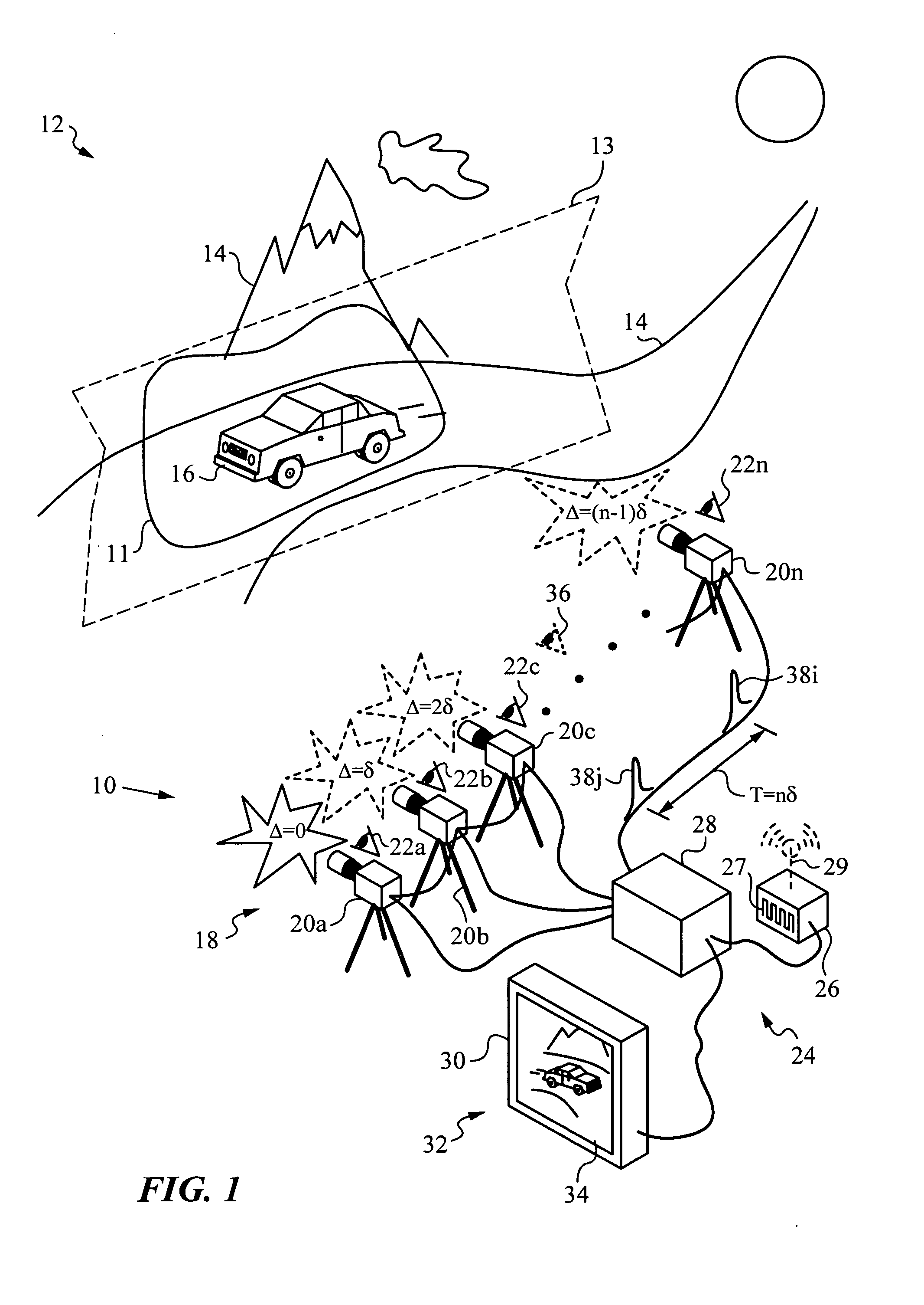
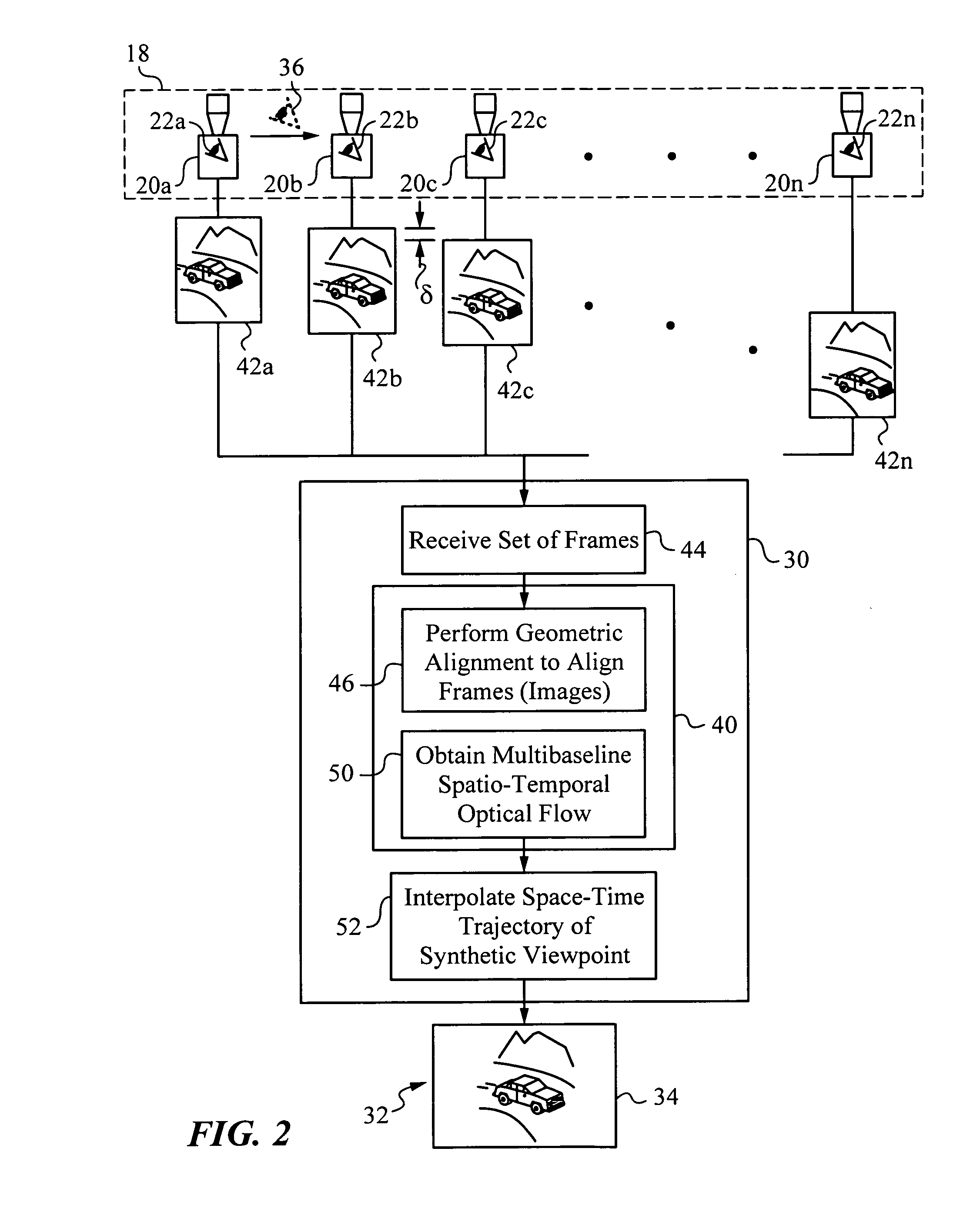
[0034] The present invention will be best understood by first reviewing FIG. 1, which illustrates a simplified schematic diagram of an apparatus 10 for capturing a three-dimensional region of interest 11 in a scene 12. Scene 12 contains static elements 14, here mountains and a road, as well as a dynamic element 16, in this case a moving car. Region of interest 11 contains dynamic element 16, i.e., the car, and its immediate surroundings. In the present embodiment, region of interest 11 is considered to be confined to a single object plane 13. It should be noted that using plane 13 is a simplifying assumption and represents only one albeit useful approach. Nonetheless, a person skilled in the art will recognize that other surfaces or geometrical assumptions about the location of region of interest 11 in scene 12 can be made.

[0035] Apparatus 10 has an array 18 of n video cameras 20a, 20b, . . . , 20n positioned for viewing region of interest 11 in scene 12. In the present embodiment ...


PUM


Abstract

This invention relates to an apparatus and a method for video capture of a three-dimensional region of interest in a scene using an array of video cameras. The video cameras of the array are positioned for viewing the three-dimensional region of interest in the scene from their respective viewpoints. A triggering mechanism is provided for staggering the capture of a set of frames by the video cameras of the array. The apparatus has a processing unit for combining and operating on the set of frames captured by the array of cameras to generate a new visual output, such as high-speed video or spatio-temporal structure and motion models, that has a synthetic viewpoint of the three-dimensional region of interest. The processing involves spatio-temporal interpolation for determining the synthetic viewpoint space-time trajectory. In some embodiments, the apparatus computes a multibaseline spatio-temporal optical flow.

Description

RELATED APPLICATIONS [0001] This patent application claims priority to U.S. Provisional Patent application 60 / 590,310 filed on Jul. 21, 2004 and hereby incorporated by reference.STATEMENT OF GOVERNMENT SPONSORSHIP [0002] This invention was supported in part by DARPA under grant Nos. F29601-00-2-0085 and NBCH-10300095, as well as by the National Science Foundation under contract No. 0219856. The U.S. Government has certain rights in the invention.FIELD OF THE INVENTION [0003] This invention relates generally to apparatus and methods for capturing a scene with an array of cameras, and more particularly for high-speed video capture. It also relates to improved apparatus and methods for processing video of dynamic scenes using an array of video cameras that are triggered to capture frames a staggered manner. BACKGROUND ART [0004] The use of separate video cameras for high-speed video capture and 3-dimensional scene or object reconstruction is known in the art. General information on mul...

Claims


Application Information

Patent Timeline
IPC IPC(8): H04N13/02
CPCH04N5/247H04N5/357H04N5/3532H04N25/531H04N25/60H04N23/90
Inventor WILBURN, BENNETTJOSHI, NEELLEVOY, MARC C.HOROWITZ, MARK
Owner THE BOARD OF TRUSTEES OF THE LELAND STANFORD JUNIOR UNIV
Learn More