Management of telecommunications connections

a technology of telecommunications connections and management equipment, applied in the field of telecommunications systems, can solve the problems of impracticality of powering the distribution points from the exchange side, and achieve the effect of retaining system stability and minimizing power consumption

Active Publication Date: 2011-11-10
BRITISH TELECOMM PLC
View PDF23 Cites 15 Cited by
  • Summary
  • Abstract
  • Description
  • Claims
  • Application Information

AI Technical Summary

Benefits of technology

[0012]Embodiments of the present invention take ad vantage of the data processing power available at the mini-DSLAM in each distribution point, and the availability at the DP of the data to perform dynamic line management (DLM), to make the DP autonomous in setting its own maximum stable DSL rate, by processing the data relating to line capabilities locally at the distribution points, and implementing any subsequent change of DLM profile locally. This approach still allows decisions on DLM profile choice to be made taking into account demands on neighboring customer terminals sharing the same DP 1. This configuration allows some of the DSLAM functions to be performed by the individual remote nodes, allowing each remote node to implement a local autonomous system using the physical layer statistics it collects, and to process them locally to provide an optimum DSL profile for each line while retaining system stability. In particular, the RAMBo functions 41 are migrated to the distribution points 1.
[0013]The operational environment of each line served by the Distribution Point 1 will be very similar, so there are advantages in implementing an autonomous DLM system at the DP. This would allow each DSL line operating from a remote node located at the DP to be optimized, based upon the local operational environment as seen at that DP.
[0014]In a fiber-to-the-distribution-point system it is impractical to power the distribution points from the exchange side because of the absence of a wired connection. The remote nodes therefore take power from the customer end of the connection. It is therefore important that power consumption is minimized.
[0016]The MLP is suitable for the field of digital line management as this application can be considered as a combination of pattern recognition (recognizing specific patterns of input line statistics) and control system (changing the DLM profile accordingly). Initially it is necessary to ‘train’ the MLP in order to optimize the physical layer performance of the line from the gathered statistics. The computational burden of implementing an MLP lies in this initial training of the system, that is, in calculating the ‘weights’ of the nodes and links. However, once trained, the MLP requires very little computational power in order to identify the target profile for a loop, given a set of physical layer statistics. This therefore results in low processing and power overheads, which is particularly desirable if power is to be taken from the customer side.
[0018]One advantage of using neural nets for such a system is that all of the processor intensive work can be performed during the training of the neural net. Once trained, the neural net is instantiated in the remote node and each analysis of the input data is a simple single iteration through the neural net, which will be just a few multiplications and additions. Therefore the computational load on the remote node processor resources will be minimal. More processing power would be required if a training algorithm is implemented to allow local adaptation at the remote node, but this training could be performed when there was plenty of spare computational resource available. As these remote nodes are powered from the CPE and that computational power (and electrical power in general) is therefore not a resource to be squandered.

Problems solved by technology

In a fiber-to-the-distribution-point system it is impractical to power the distribution points from the exchange side because of the absence of a wired connection.

Method used


Image

  • Management of telecommunications connections
  • Management of telecommunications connections
  • Management of telecommunications connections

Examples


Embodiment Construction

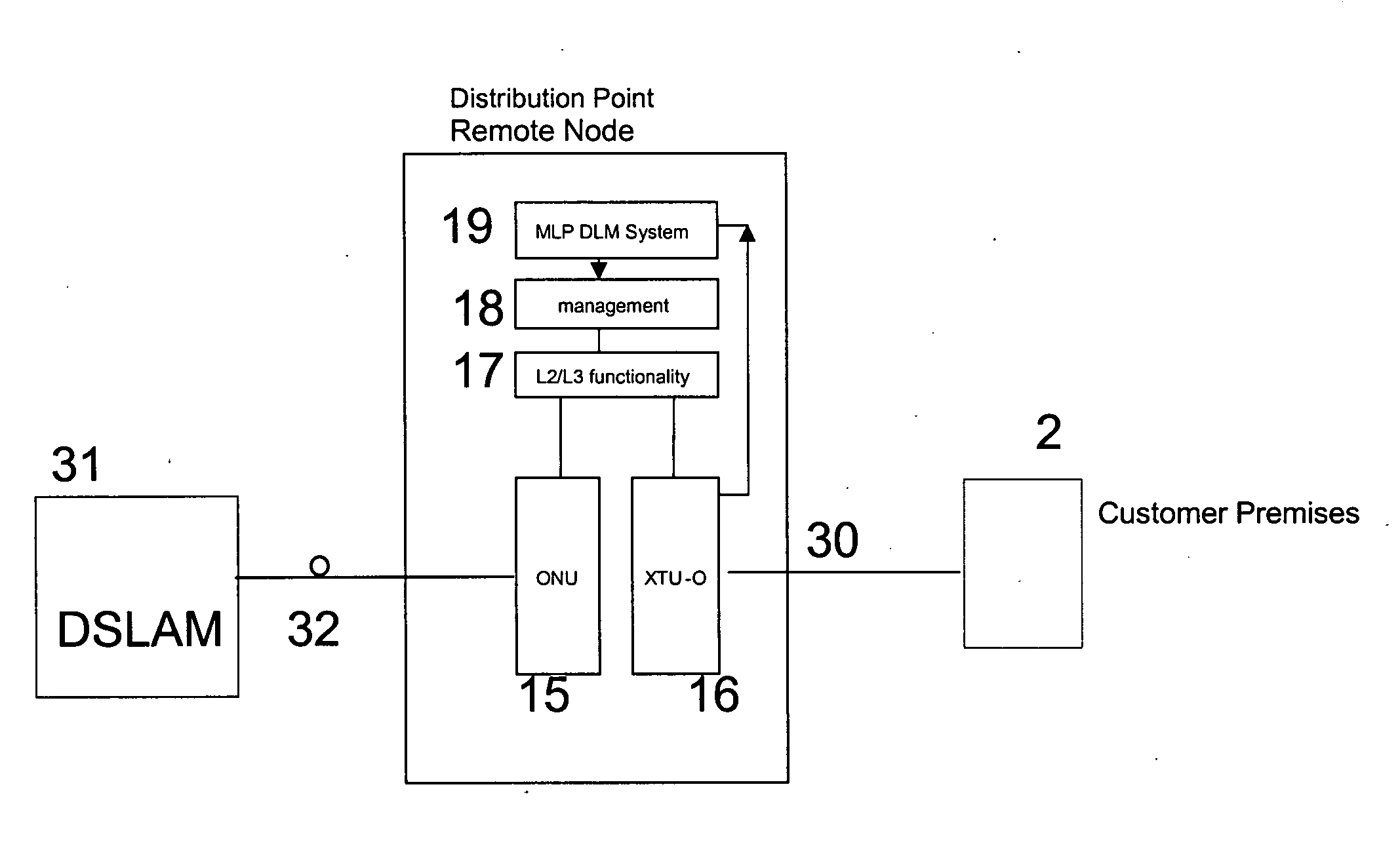
[0026]It should be understood that FIGS. 3 to 5 illustrate the functional elements of the system, which may in practice be embodied in one or more electronic components or in software.

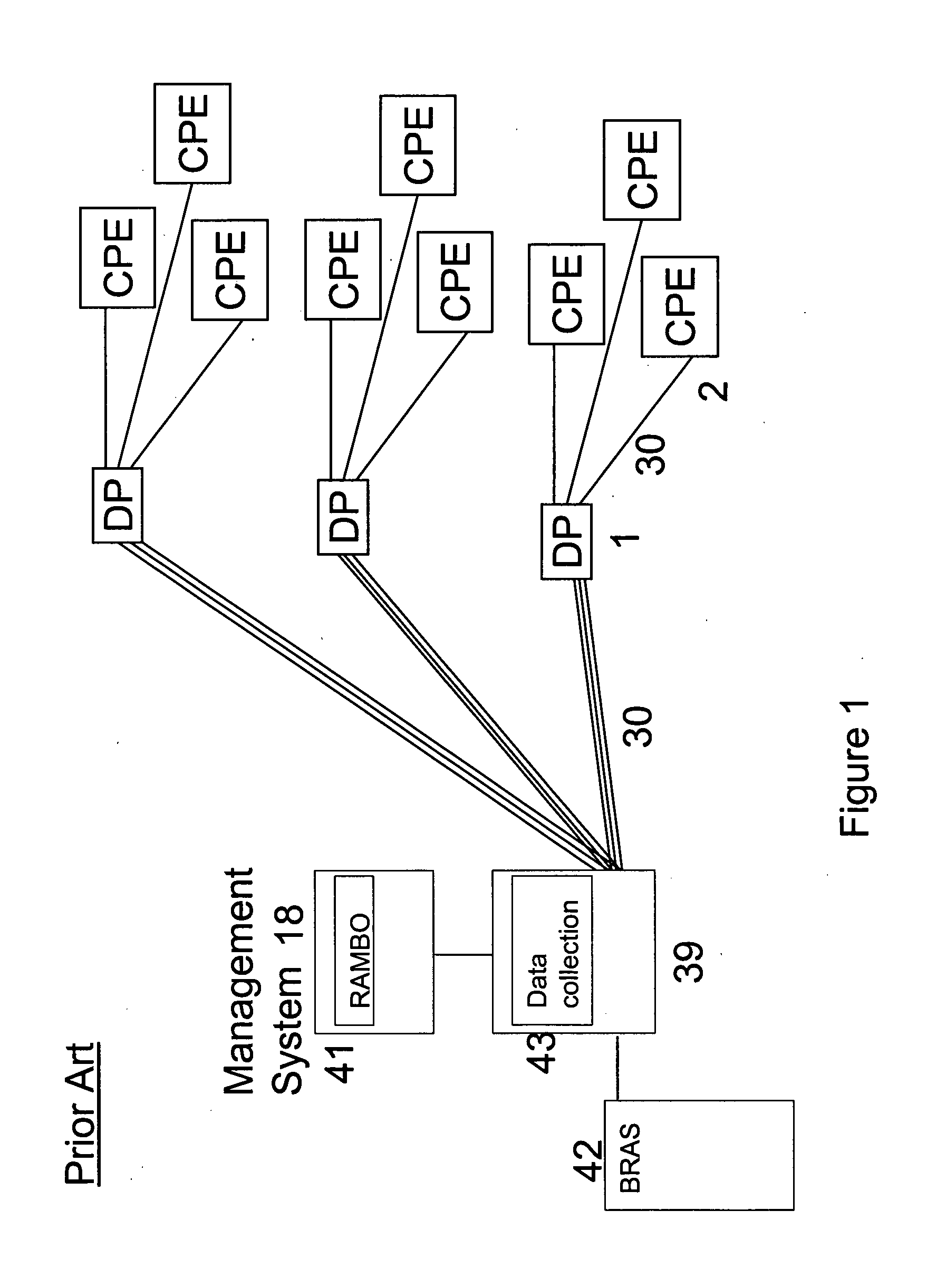
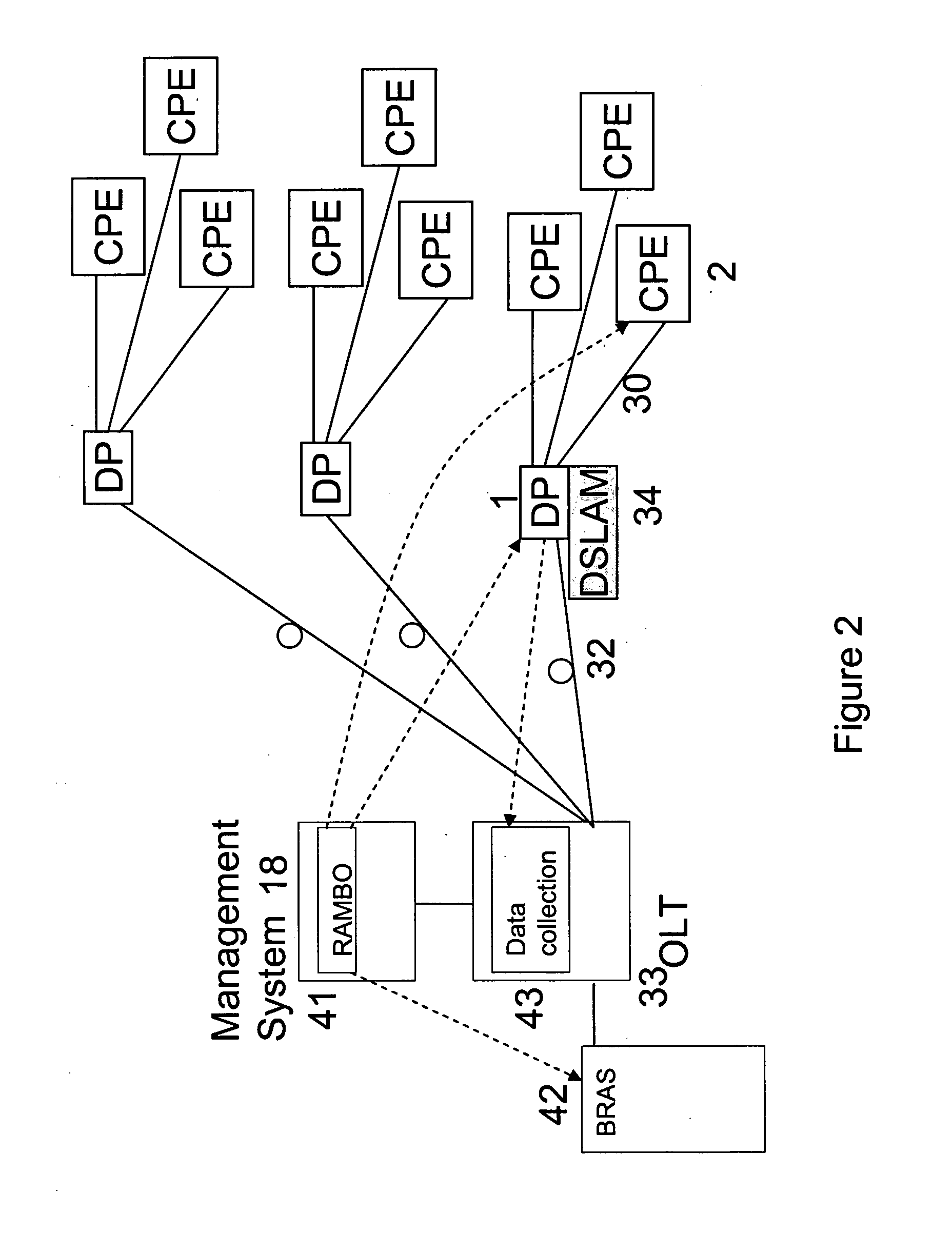
[0027]FIG. 3 illustrates the configuration of the system, and by comparison with FIG. 2 the modifications made according to the invention can be understood. The principal difference is that the Rate Adaptive Management Box (RAMBo) 41 has been migrated from the management system 18 associated with the optical line termination 33 in the exchange to the distribution point 1. (It will be understood that each distribution point can be similarly equipped). The data collection and processing functions controlling the data rate to be used over the DSL link 30 can therefore be performed at one end of that link. Thus, instead of measurement data sent from the DP 1 to the RAMBo 41 in an exchange-based management system 18, and the resulting data rate required returned to the DP 1, the RAMBo 41 located in the DP 1...


PUM


Abstract

A network distribution, point (1) for operation as a node in a telecommunications system intermediate between a remote access server (41) and a plurality of individual termination points (1) served from the remote access server (41) by respective digital subscriber loops (30), in particular at an optical fibre / copper wire interface (17), incorporates a dynamic line management system (18) for processing data relating to the capabilities of each of the digital subscriber loops (30), and generating a pro file of each digital subscriber loop (30) for transmission to the remote access server (49) to allow control of the transmission of data to the individual termination points.

Description

RELATED APPLICATIONS[0001]The present application is a National Phase entry of PCT Application No. PCT / GB2010 / 000016, filed Jan. 7, 2010, which claims priority from European Patent Application No. 09250095.8, filed Jan. 15, 2009, the disclosures of which are hereby incorporated by reference herein in their entirety.TECHNICAL FIELD[0002]This invention relates to telecommunications systems and in particular to the management of network equipment interfacing between a network and individual customer premises systems. Such equipment is widely dispersed geographically, and has to operate without direct human supervision and in a wide variety of environments and circumstances.BACKGROUND ART[0003]As shown in FIG. 1, in conventional Digital Subscriber Loop (DSL) services, provided from the exchange 39 (or cabinet), each customer premises 2 has a dedicated physical connection 30 to the DSL access multiplexer (DSLAM) 31 in the exchange 39. The connections from the exchange 39 to several diffe...

Claims


Application Information

Patent Timeline
Patent Type & Authority Applications(United States)
IPC IPC(8): H04L12/66H04L12/28
CPCH04L12/2869H04L41/0806H04L41/0853H04L41/12H04L41/16H04Q2213/13349H04Q11/04H04Q2213/13039H04Q2213/13092H04Q2213/13109H04M3/306
Inventor COOPER, IAN ROBERT
Owner BRITISH TELECOMM PLC
Why Eureka
Try Eureka