Series wiring of highly reliable light sources

Active Publication Date: 2007-02-08
SILICON VALLEY BANK
View PDF99 Cites 30 Cited by
  • Summary
  • Abstract
  • Description
  • Claims
  • Application Information

AI Technical Summary

Benefits of technology

[0011] Another advantage of the present invention is that connecting the LED's in series provides all of the LED's in the series with the same amount of current so that the LED's have the same brightness.
[0012] This invention provides a lighting module comprising an array of LED's consisting of plural columns and rows, wherein each row of LED's in each column is connected in series and each column is connected in parallel. The LED array may be connected in series to one or more LED arrays. Each column in the LED array may contain at least one row of, for example, three LED's. Each column in the LED array may contain, for example, twenty-five rows of LED's. The LED array may contain, for example, thirteen columns.
[0013] T

Problems solved by technology

Such strings present unique problems for the electrical engineer.
However, stringing the components together in series presents a problem because if one of the components in the string fails, it will result in the failure of the entire string.
For example, in a string of holiday lights wired in series, if one light fails the entire string also fails.
However, such wiring requires higher current and lower voltage.
This presents

Method used


Image

  • Series wiring of highly reliable light sources
  • Series wiring of highly reliable light sources
  • Series wiring of highly reliable light sources

Examples


Embodiment Construction

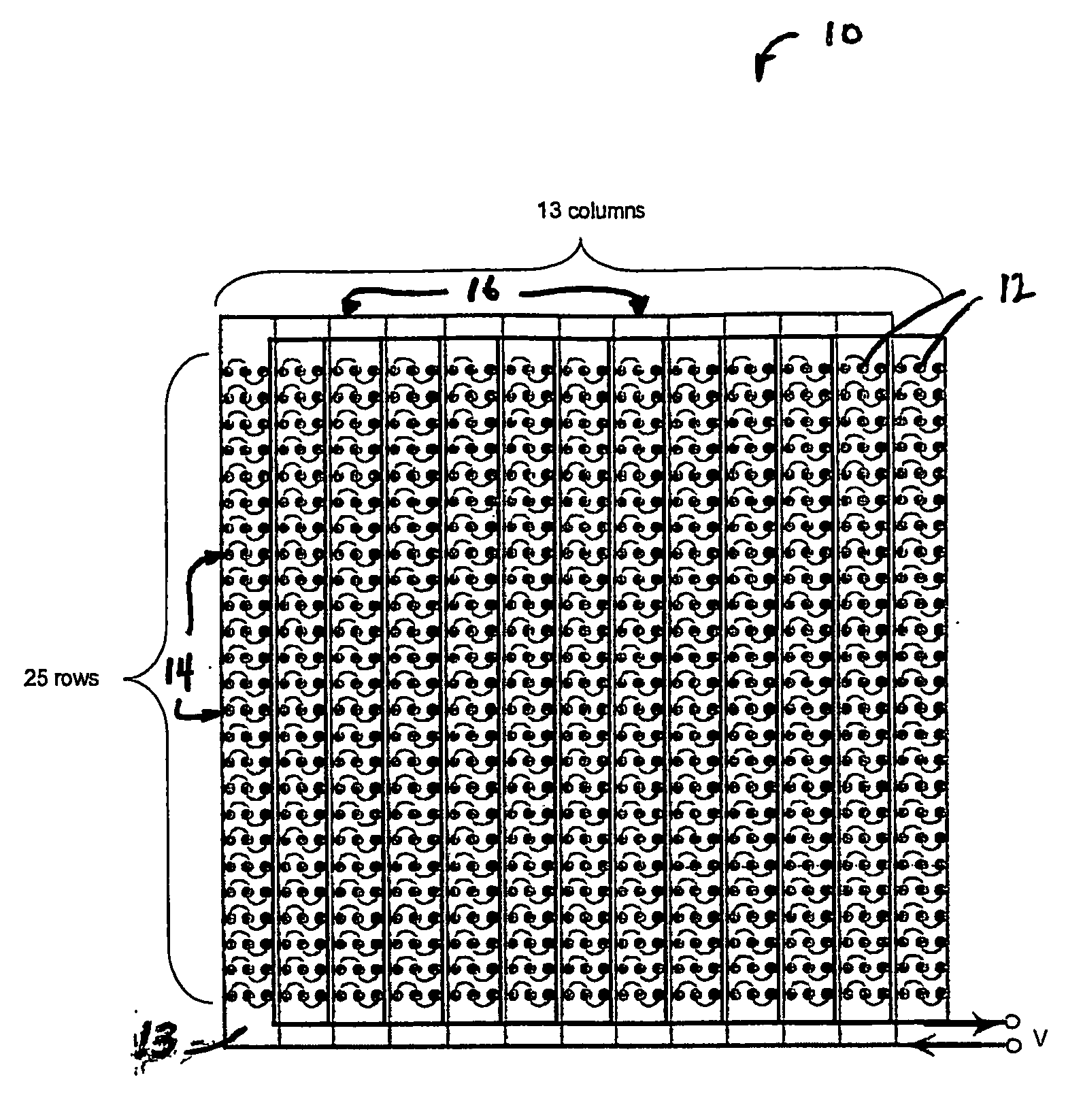
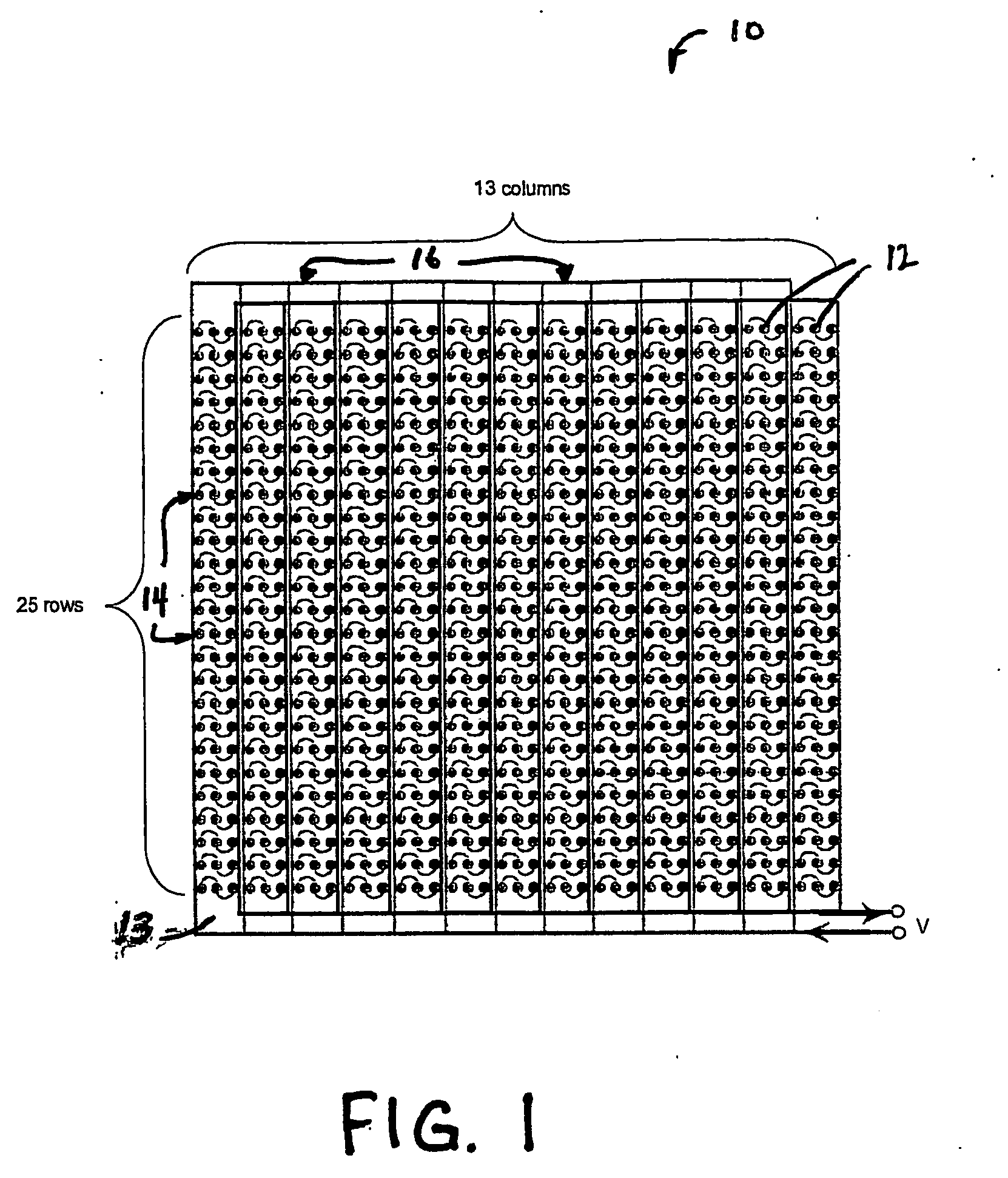
[0019] Representative embodiments of the present invention are shown in FIG. 1, wherein similar features share common reference numerals.

[0020] As shown in FIG. 1, an LED array 10 is shown that is wired in a series / parallel combination. The LED array 10 includes a plurality of individual LED's 12 mounted on a substrate 13 and arranged in rows 14 and columns 16. Each column 16 includes plural rows 14 of LED's 12 with, for example, three LED's 12 in each row 14. There may be, for example, twenty-five rows 14 in each column 16. The LED's 12 in each row 14 are wired in series and each column 16 is wired in parallel. Since the LED's 12 in each row 14 are wired in series it is ensured that if one LED 12 fails only the other LED's 12 in that series will fail also. The loss the LED's 12 in a single row 14 in the total array 10 has only a minimal impact on the total brightness of the array 10 since it consists of many LED's 12.

[0021] In this example, the total voltage required to drive the...


PUM


Abstract

The light array of this invention includes a number of columns and rows of LED's connected in a series/parallel combination. The series parallel combinations effectively optimize the impedance, accommodate failure rate, facilitate light mixing, provide a means of imbedding redundancy, and common cathodes or anodes. This arrangement provides a superior light source for consumer, industrial and specialty markets in respect to mean time between failure, process control, radiant intensity, wavelength mixing, power requirements and other characteristics of the light source. Each column includes a number of rows of plural LED's. The LED's in each row are wired in series and each column is wired in parallel so that if one LED fails only the LED's connected in series with the failed LED will also fail. There is redundancy in the circuit as well as the arrays so that if there are failures different current carrying elements or different series LEDS will automatically by powered on. The array may be connected in series with one or more LED arrays to form a module. Multiple modules may be connected in series with other multiple modules.

Description

[0001] This invention claims the benefit of co-pending U.S. Provisional Application No. 60 / 516,381, entitled “Series Wiring of Highly Reliable Light Sources,” filed Oct. 31, 2003, the entire disclosure of which is hereby incorporated by reference as if set forth in its entirety for all purposes.BACKGROUND OF THE INVENTION [0002] Solid state lighting devices such as, for example, light emitting diodes (LED's) are used for a number of applications. One type of such solid state lighting device is disclosed in International Patent Application No. PCT / US03 / 14625, filed May 28, 2003, entitled High Efficiency Solid-State Light Source And Methods Of Use And Manufacture, the details of which are hereby incorporated by reference. [0003] There are numerous applications where a long string of devices, such as, for example, LED's, need to be connected electrically. Such strings present unique problems for the electrical engineer. On the one hand, there is a desire to string the components in ser...

Claims


Application Information

Patent Timeline
IPC IPC(8): F21V21/00H05B
CPCH05B33/0809H05B33/089H05B33/0821H05B33/0818Y10S362/80H05B45/40H05B45/00H05B31/50H05B45/52
Inventor BEDSON, JON R.MCNEIL, THOMAS R.OWEN, MARK D.
Owner SILICON VALLEY BANK
Why Eureka
Try Eureka