
Transmission parameter control device

a control device and transmission parameter technology, applied in the field of data transmission, can solve the problems of complex control, inconvenient, and inability to control, and achieve the effect of improving the transmission quality of real-time media

Inactive Publication Date: 2007-02-08
FUJITSU LTD
View PDF3 Cites 55 Cited by
  • Summary
  • Abstract
  • Description
  • Claims
  • Application Information

AI Technical Summary

Benefits of technology

[0012] The present invention is contrived to solve at least one of the problems, and an object of the present invention is to provide a transmission parameter control apparatus that can improve the transmission quality of the real-time media in the transmission route that includes the wireless section in at least a part of the transmission route.

Problems solved by technology

Therefore, as shown in the patent document 1 and the patent document 2, to change transmission rate and the like according to the communication environment of the particular receiver at each time makes control complicated and inconvenient as the number of terminals that perform data communication with the terminal increase.
This means that data transmission efficiency of the system as a whole degrades.
However, since signal transmission schemes (packet frame configuration, for example) between the wireless section and a cable section are different, enhancing the wireless communication quality does not necessarily directly enhance the transmission quality of the real-time media.
Therefore, in the conventional transmission system including the wireless section, there is fear that the transmission quality of the real-time media is not properly maintained.
On the other hand, when a target value of the transmission quality of the real-time media is set to be excessively high, redundant communication resources and calculation load become necessary to achieve the target high quality, so that it may exert bad effects to the data transmission efficiency of the whole system.

Method used


Image

  • Transmission parameter control device
  • Transmission parameter control device
  • Transmission parameter control device

Examples


Embodiment Construction

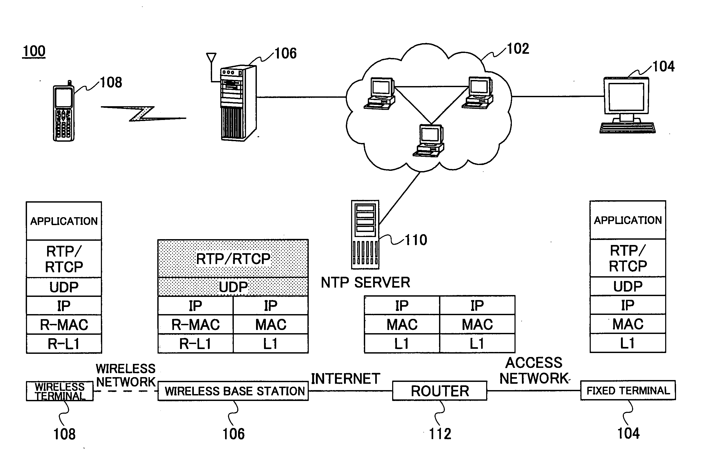
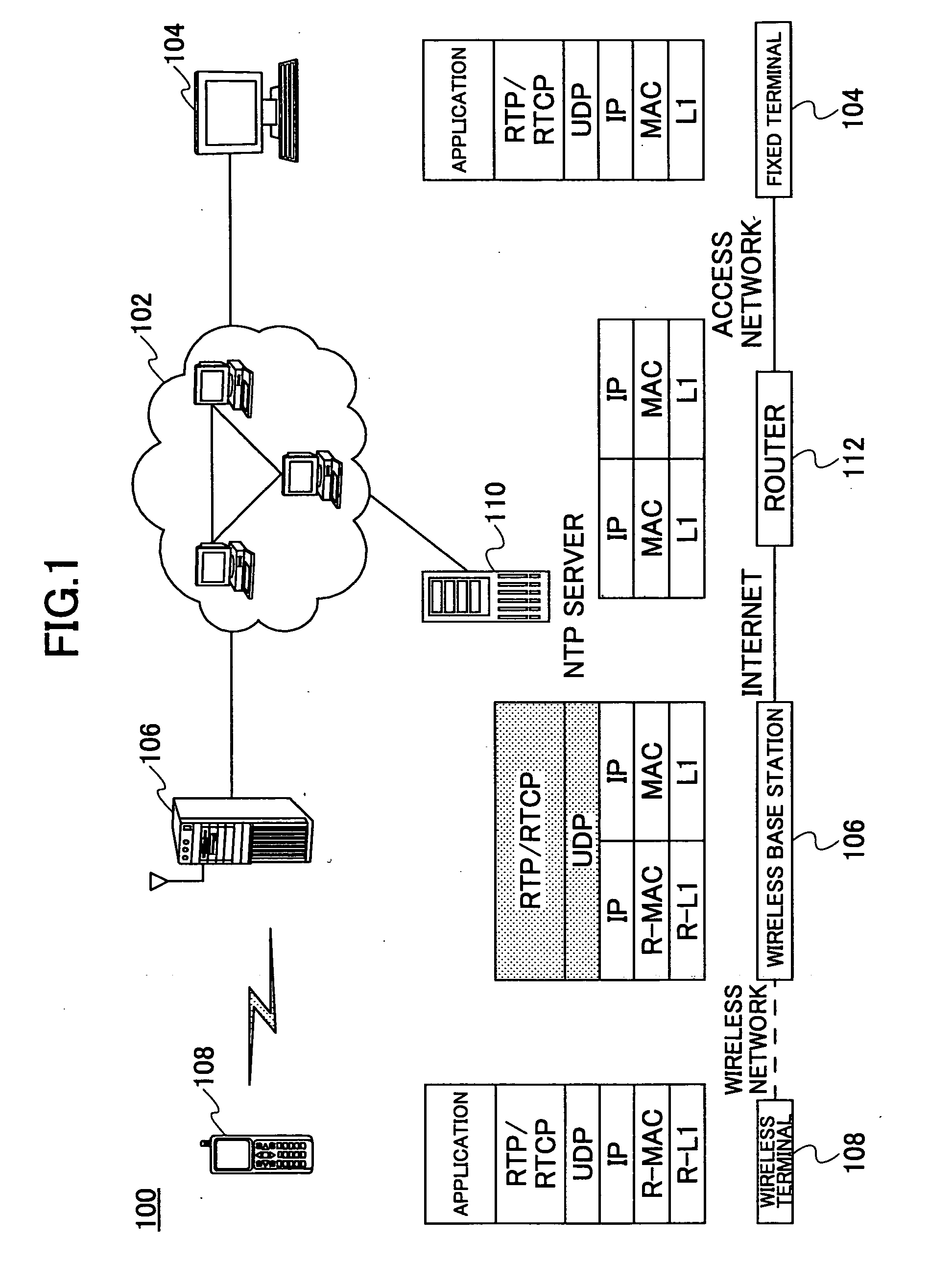
[0028]FIG. 1 shows a communication system performing real-time media streaming in an embodiment of this application. Generally, components appearing in FIG. 1 have reference numbers starting with “1”. The communication system 100 includes a fixed terminal 104 connected to a network, and the fixed terminal 104 distributes real-time media such as voice or video data. The communication system 100 includes one or more wireless base station 106. The wireless base station 106 can communicate with the mobile terminal 108 via a wireless link. The mobile terminal 108 is an apparatus conforming to RTP / RTCP, such as a portable telephone, a personal computer, a PDA and the like. Although only one wireless base station 106 and one mobile terminal 108 are shown for the sake of simplicity, a plurality of these may exist actually. Further, the communication system 100 includes an NTP (Network Time Protocol) server 110. The NTP server 110 distributes a reference time for causing the various communic...


PUM


Abstract

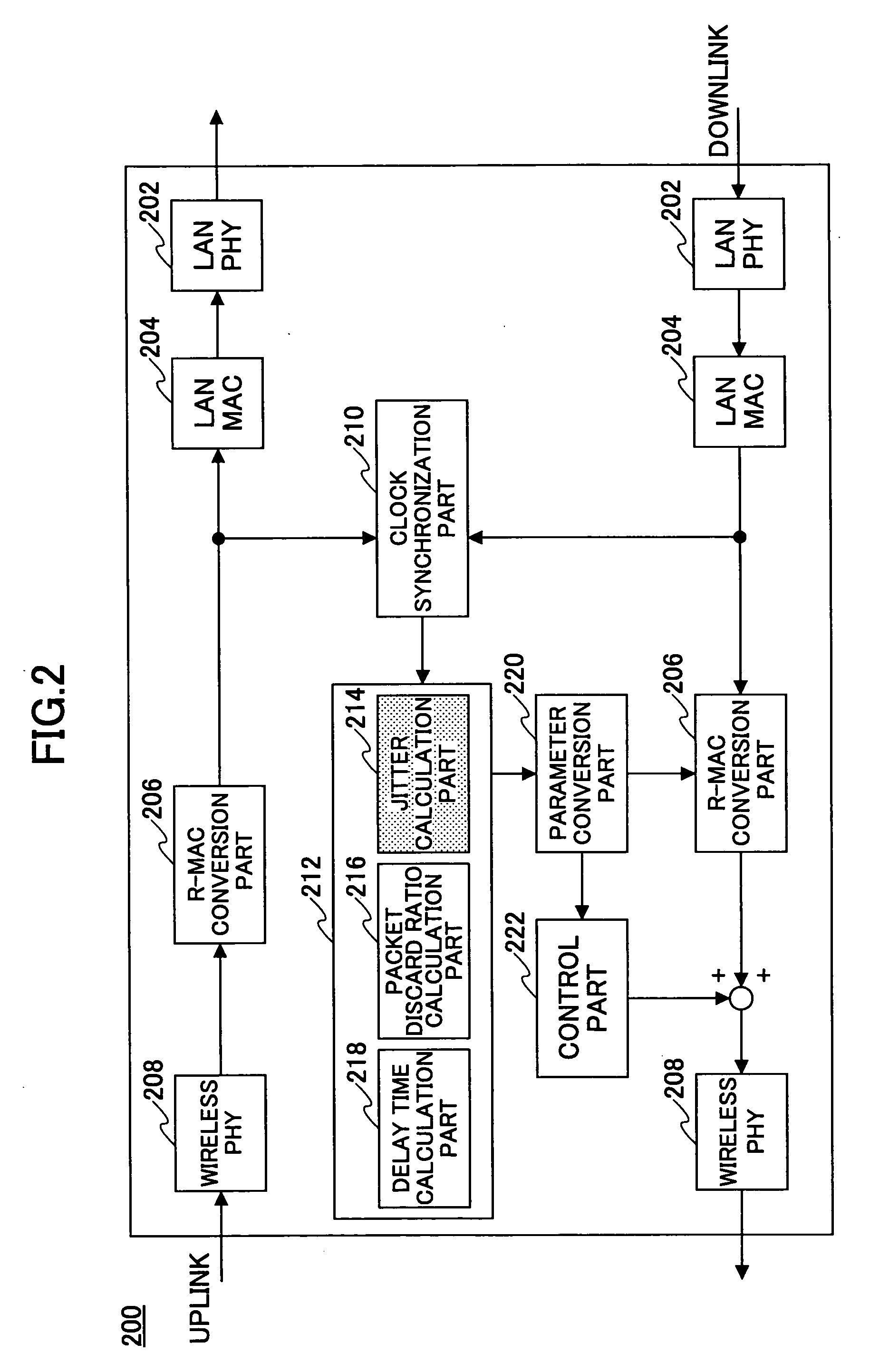
An object of the present invention is to provide a transmission parameter control apparatus that can improve transmission quality of real-time media in a transmission route that includes a wireless section in at least a part of the transmission route. According to the present invention, a transmission parameter control apparatus 200 that is connected to a terminal 104 via a network 102 and that is connected to a mobile terminal 108 via a wireless link, is provided. The apparatus includes: an obtaining part 210 for obtaining a quality parameter indicating transmission quality corresponding to the wireless link from signals of downlink and uplink transmission routes; and an adjustment part 220 for adjusting a value of a transmission parameter determining a transmission scheme in the wireless link according to the quality parameter.

Description

CROSS-REFERENCE TO RELATED APPLICATION [0001] This application is a U.S. continuation application filed under 35 USC 111(a) claiming benefit under 35 USC 120 and 365(c) of PCT application PCT / JP2003 / 011575, filed on 10 Sep., 2003. The foregoing application is hereby incorporated by reference.BACKGROUND OF THE INVENTION [0002] 1. Field of the Invention [0003] The present invention generally relates to a technical filed of data transmission. More particularly, the present invention relates to a transmission parameter control apparatus for performing data transmission using RTP (Real-time transport protocol) and RTCP (RTP control protocol) on a transmission route including a wireless section in a part of the transmission route. [0004] 2. Description of the Related Art [0005] The RTP and / or the RTCP are protocols for transmitting real-time media such as voice signals and video signals. The real-time media are generated from data that are generated continuously in terms of time. For repr...

Claims


Application Information

Patent Timeline
IPC IPC(8): H04Q7/00H04L1/00H04L12/70H04L29/06H04L29/08H04W28/00H04W28/18H04W80/02H04W84/12H04W88/08
CPCH04L1/0026H04L65/80H04W28/18H04L29/06027H04L1/0001H04L1/0009H04L1/1867H04L1/205H04L47/2416H04L47/2458H04L47/25H04L47/283H04W28/0236H04W28/10H04L65/65H04L47/10H04L65/1101H04W8/04
Inventor IWAMURA, NAOTOYAMAGUCHI, SEIICHIMIYAGAWA, YASUSHIHATAKEYAMA, SHINYA
Owner FUJITSU LTD
Learn More