Video reproducing device

Active Publication Date: 2007-02-08
MAXELL HLDG LTD
View PDF12 Cites 29 Cited by
  • Summary
  • Abstract
  • Description
  • Claims
  • Application Information

AI Technical Summary

Benefits of technology

[0013] According to the second configuration of the present invention, the first index screen, the second index screen, and the normal video can be sequentially switched by a single operation. The operation switch

Problems solved by technology

When one of the video format and the audio format of the moving image file is not matched with the format on the device side, they are both invalid and the detailed matched status cannot be clarified.
In additi

Method used


Image

  • Video reproducing device
  • Video reproducing device
  • Video reproducing device

Examples


Example

Embodiment 1

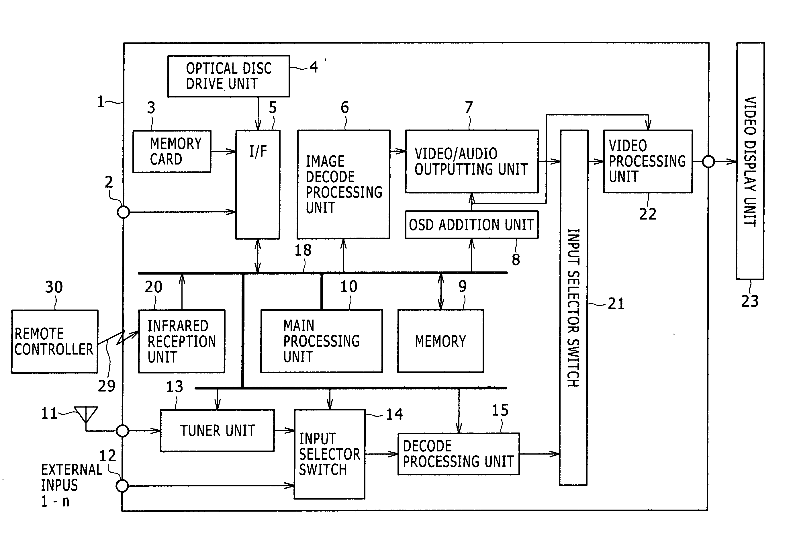
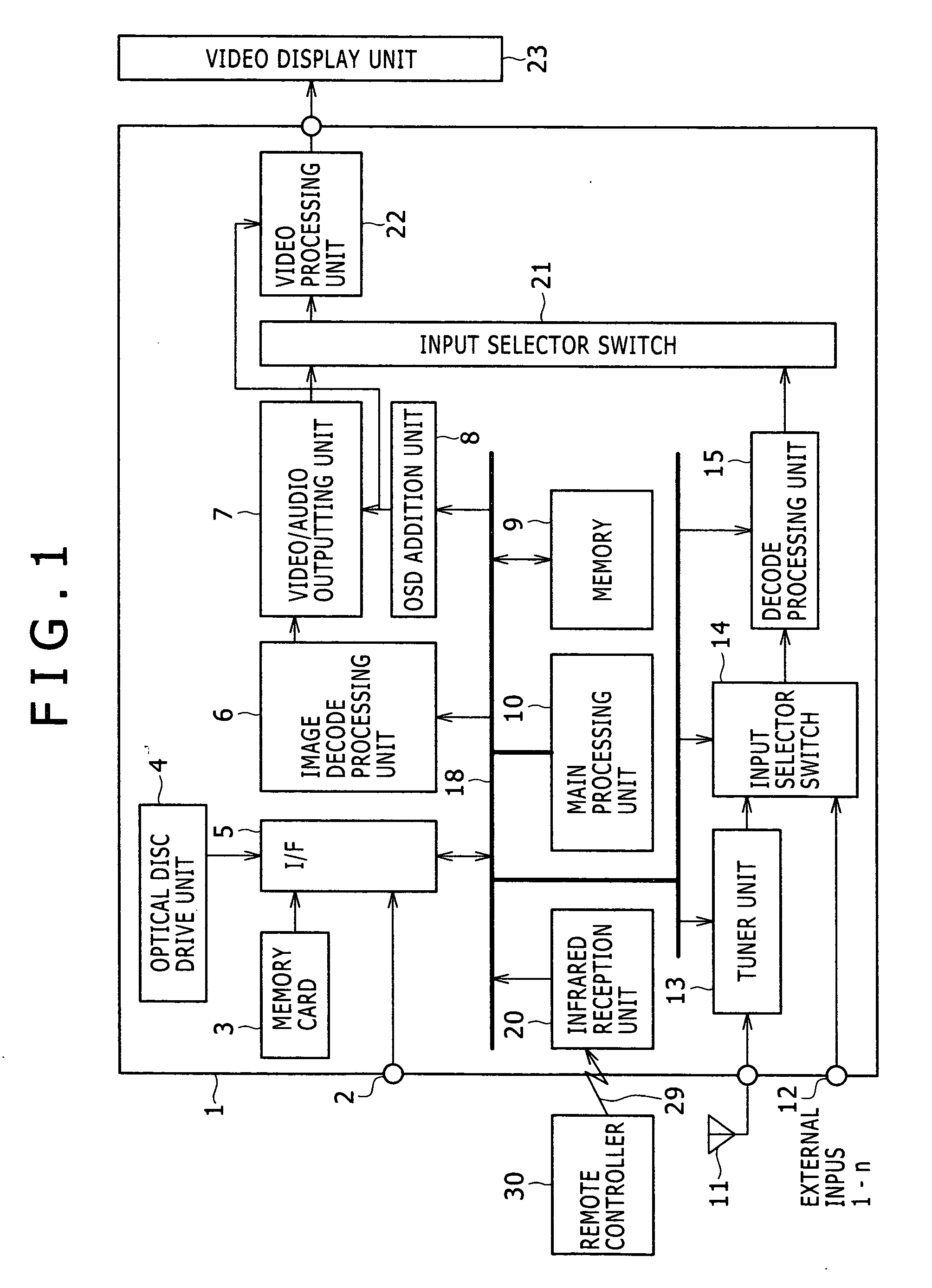
[0029]FIG. 1 is a schematic block diagram showing one configuration example of a video reproducing device according to Embodiment 1. In FIG. 1, a video reproducing device 1 is operated by a remote control signal 29 transmitted from a remote controller 30 using infrared rays. An infrared reception unit 20 which receives the remote control signal 29 converts it to an electric signal to output it via a bus line 18 to a main processing unit 10. The main processing unit 10 is an arithmetic controller including a CPU (Central Processing Unit) and controls components configuring the video reproducing device 1 as necessary in accordance with a program stored in a memory, not shown, based on the received remote control signal for performing predetermined processing.

[0030] The video reproducing device 1 has a USB input terminal 2, the mounting mechanism of a memory card 3, not shown, and an optical disc drive unit 4, to which image data recorded by an external recording device (...

Example

[0060] Embodiment 2 of the present invention will be described using FIG. 7.

[0061] As in the block schematic configuration of FIG. 1, a related art video reproducing device typically has a TV broadcast reception function and plural external inputs such as VCRs in addition to the recording medium reproducing function and switches recording medium reproduction, reception reproduction, and external input video reproduction based on user operation. For convenience of the description, the switch between the reproductions will be called “input switch” according to usage.

[0062]FIG. 7 is a diagram of assistance in explaining an input switch method related to a recording medium according to Embodiment 2. In FIG. 7, elements having common functions to FIGS. 5 and 6 are indicated by the same reference numerals and the overlapped description is omitted.

[0063] In FIG. 7, an input switch button 31 provided on the remote controller 30 is a button switching an output of the tuner unit 13 and ext...

Example

Embodiment 3

[0072] Embodiment 3 according to the present invention will be described using FIGS. 8A to 10C.

[0073]FIGS. 8A and 8B are diagrams showing an index screen and changes in brightness in a screen vertical direction in the related art. FIG. 9 is a diagram of how the index screen is viewed in the related art. FIGS. 10A to 10C are diagrams showing an index screen and changes in brightness in a screen vertical direction according to Embodiment 3.

[0074] As shown in FIG. 8A, in the related art, an index screen 111 often displays thumbnail images 151 on a background screen 112 of a single color such as gray or blue. The average brightness level of the thumbnail images 151 is typically about 40%. Changes in brightness in the screen vertical direction in that case is shown in FIG. 8B. As shown in FIG. 8B, the brightness level difference in the screen vertical (hereinafter, abbreviated as “V”) direction is large in the gray back portion of the background screen 112 and the thumbnai...


PUM


Abstract

The present invention provides a video reproducing device which provides a function of reproducing a still image file and a moving image file recorded onto a recording medium in plural formats so that a user can easily identify a matched statuses of the files in the video reproducing device and can select and operate a target file as well as a control method therefor. The present invention displays an index screen in which thumbnails of a still image file and a moving image file in plural formats read from a recording medium are arrayed and further displays icons for clarifying a match relation between the video reproducing device and the files.

Description

CLAIM OF PRIORITY [0001] The present application claims priority from Japanese application serial no. JP 2005-229014, filed on Aug. 8, 2005, the content of which is hereby incorporated by reference into this application. BACKGROUND OF THE INVENTION [0002] (1) Field of the Invention [0003] The present invention relates to a video reproducing device which can reproduce and display a still image file and / or a moving image file recorded onto a removable recording medium such as a memory card. [0004] (2) Description of the Related Art [0005] There exists a video reproducing device having the function of reproducing a still image file and / or a moving image file recorded onto a removable recording medium. The moving image / still image file is recorded onto the recording medium in various formats (such as JPEG and MPEG) by a recording device such as a digital still camera or a PC. For instance, JP-A Nos. 2005-70858 and 2004-215281 disclose a technique of displaying on a screen that the forma...

Claims


Application Information

Patent Timeline
IPC IPC(8): H04N7/00G11B27/00G11B27/34H04N5/445H04N5/76H04N5/907H04N5/91H04N5/93
CPCG11B27/34G11B27/105
Inventor OSHIKIRI, MASATOTAKATA, HARUKIKITAZUME, AKIRAUZAWA, TAKEHIRO
Owner MAXELL HLDG LTD
Why Eureka
Try Eureka